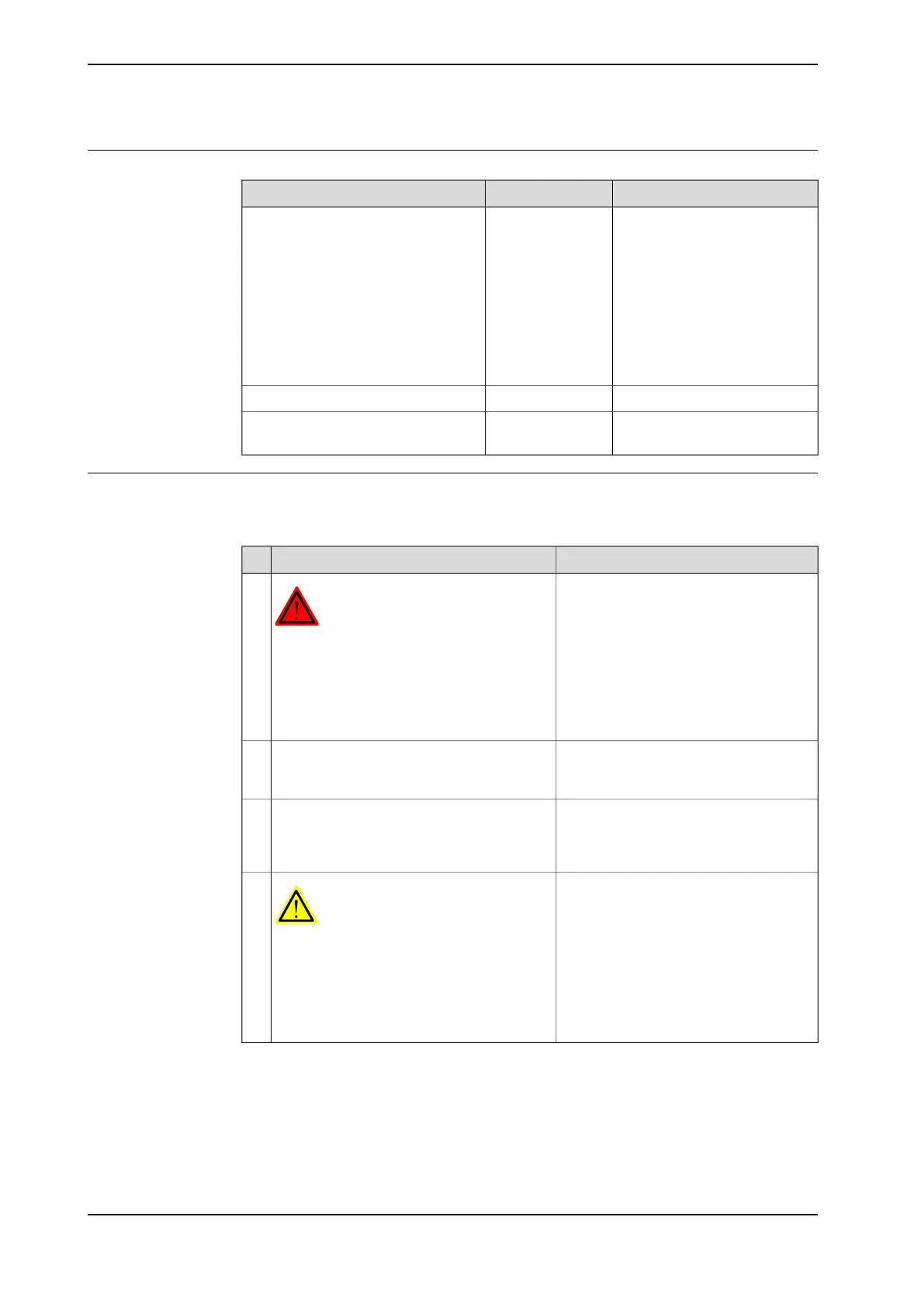
Required equipment
NoteArticle numberEquipment, etc.
Includes:
• one stop (+15°/ -7.5°),
3HAC025366-001
• one stop (+7.5°/ -15°),
3HAC025367-001
• attachment screws and
washers
• document for movable
mech.stop, 3HAC025204-
002
3HAC025204-003Movable mechanical stop set, axis 1
(+15°/-7.5°)
-Standard toolkit
Article number is specified in
section References on page 10.
-Technical reference manual - System
parameters
Installation, mechanical stops axis 1
Use this procedure to fit the additional mechanical stops to axis 1 of the robot. An
assembly drawing is also enclosed with the product.
NoteAction
DANGER
Turn off all:
• electric power supply to the robot
• hydraulic pressure supply to the robot
• air pressure supply to the robot
Before entering the robot working area.
1
Tightening torque: 120 Nm.Fit the additional mechanical stop to the
frame according to the figure Mechanical
stops, axis 1 on page 91.
2
The system parameters that must be
changed (Upper joint bound and Lower
joint bound) are described in Technical
reference manual - System parameters.
Adjust the software working range limitations
(system parameter configuration) to corres-
pond to the mechanical limitations.
3
WARNING
If the mechanical stop pin is deformed after
a hard collision, it must be replaced!
Deformed movable stops and/or additional
stops as well as deformed attachment
screws must also be replaced after a hard
collision.
4
92 Product manual - IRB 460
3HAC039842-001 Revision: P
© Copyright 2012-2018 ABB. All rights reserved.
2 Installation and commissioning
2.5.2 Mechanically restricting the working range of axis 1
Continued

 Loading...


