2 Installation and commissioning
2.6.5. Installation of position switches (option)
3HAC022033-001 Revision: K130
© Copyright 2004-2011 ABB. All rights reserved.
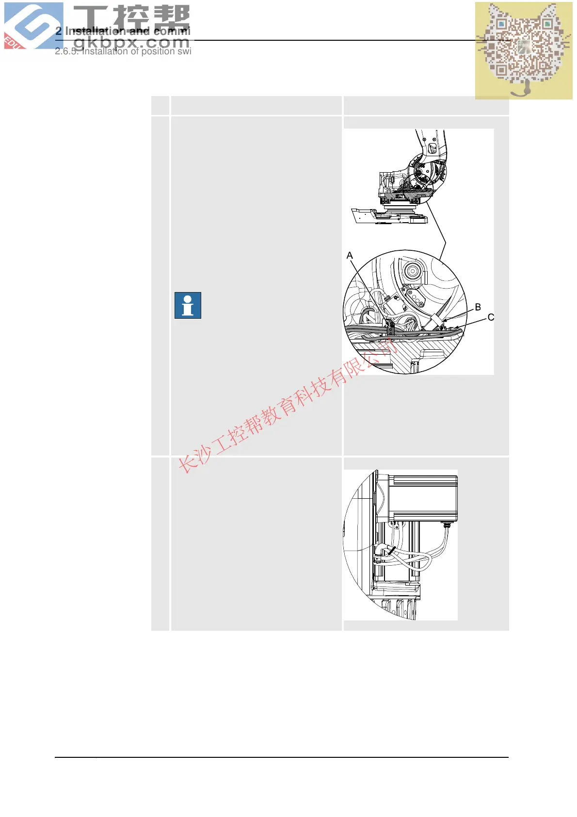
5. Run and secure the cabling inside the frame
as detailed below and as shown in the
figure to the right:
• Secure the cable bracket (A) to the
bracket of the robot cabling.
• Run the cable for the fan of axis 1 or
2 under the robot cabling and
through the side of the frame at
motor axis 1.
• Secure the cabling going up to the
axis 3 fan and position switch with
existing velcro strap (B), attached
around the robot cabling.
• Connect the connector R2.SW2 to
the position switch of axis 2.
NOTE!
There is a risk of the balancing device
damaging the fan cable if it is not protected
by correct routing underneath the robot
cabling!
xx0500002309
A. Cable bracket, frame. Also shown
in the figure Cable harness for
position switches and fans, axes 1-
3 on page 128.
B. Velcro strap
C. Connector R2.SW2
6. Connect the connector R3.FAN2 to the fan
of either axis 1 or axis 2.
If no fan is used, strap the cabling together
with the motor cabling so that the connector
stays close to the frame, as shown in the
figure to the right.
xx0500002312
Action Note
Continued
Continues on next page