2 Installation and commissioning
2.6.5. Installation of position switches (option)
1313HAC022033-001 Revision: K
© Copyright 2004-2011 ABB. All rights reserved.
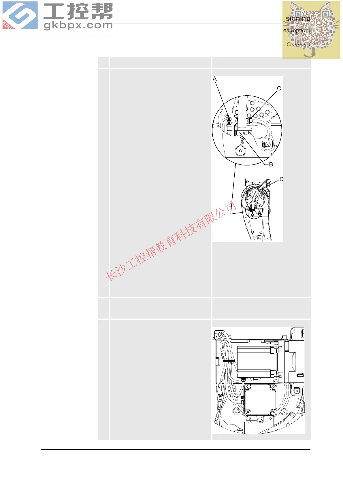
7. Run the remaining cable harness up
through the lower arm and:
• secure with the bracket, lower arm,
as shown in the figure to the right.
• connect the connector R2.SW3 to
the position switch of axis 3.
• secure the cable going to the fan of
axis 3, together with the robot
cabling with a velcro strap.
xx0500002313
A. Bracket, lower arm. Also shown in
the figure Cable harness for
position switches and fans, axes 1-
3 on page 128.
B. Bracket for robot cabling
C. Connector R2.SW3
D. Velcro strap
8. Secure the axis 3 fan cable with the bracket,
upper arm.
Shown in the figure Cable harness for
position switches and fans, axes 1-3 on
page 128.
9. Connect the connector R3.FAN3 to the fan
of axis 3. If no fan is used, strap the cable
together with the robot cabling.
xx0500002314
Action Note
Continued
Continues on next page