101510 Rev. AG Page 3–
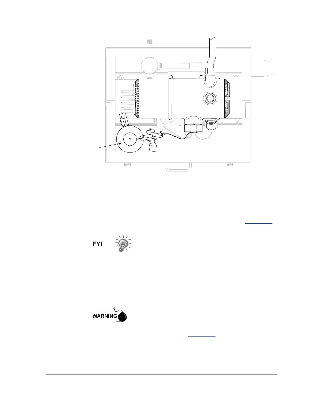
Figure 3-42 Calibration Bottle Location
3.22 Calibration Gas Regulator Installation
The following instructions are valid for all installations.
3.22.1 Materials
• Calibration blend regulator assembly with low pressure switch (see Figure 3-43
)
• Installed calibration gas bottle
These instructions assume that the carrier gas bottle has
been installed.
3.22.2 Instructions
1) Remove the protective cap from the high pressure inlet, if required.
2) Insert the ferrule on the regulator high pressure inlet into the calibration gas
bottle outlet.
3) Screw the nut onto the thread and tighten.
4) Check for leaks.
Do not connect the low pressure switch directly to the NGC
without a barrier.
5) Remove the J2 field wiring connector from the NGC termination panel located
inside the rear of the main enclosure (see Figure 3-44
).
6) Using a small flat blade screw driver, loosen DI2 pins 3 and 4.
7) Insert the red wire into the (+) terminal (pin 3).
8) Retighten pin 3.
CALIBRATION BLEND BOTTLE
CYLINDER: M009
FITTINGS: CGA180