PCS100 UPS-I User Manual 47
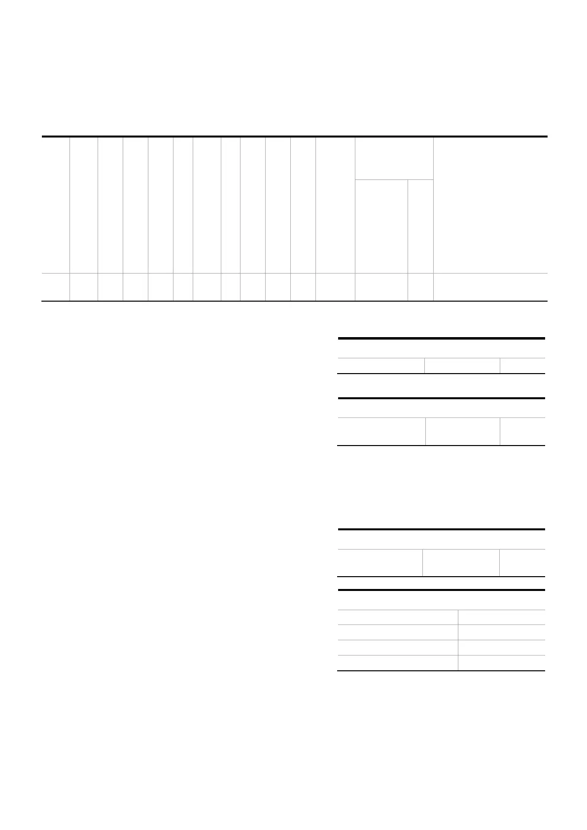
1. PCS100 UPS-I model selection
Based on application load requirements and PCS100 UPS-I Ultracapacitor model tables, the closest larger
kVA rating PCS100 UPS-I model can be selected.
Autonomy time
Sec (Rated kVA @ 0.8PF)
Autonomy time
Sec (Rated kVA @ 1.0PF)
Inverter Rated Current
[A]
Utility Disconnect Rated
Current
A
Terminal Position
(Utility &
Load)
Airflow
[(m
3
/min)
Standby
]
Fault Capacity
(lcw) kA /
Withstand Period
ms
PCS100-12-400/50-04-
L-EC02
2. Application active load calculation
First it is necessary to determine the kW rating of the load.
Either take the load kW if known, or multiply the load kVA by the
Power Factor to determine the Load kW.
3. Energy storage rating determination
In this step it is necessary to determine number of
Ultracapacitor strings required.
Ultracapacitor energy storage is based on the number of parallel
connected Ultracapacitor strings as defined in the PCS100 UPS-I
Type code (ECxx: where xx defines number of parallel connected
Ultracapacitor strings). Storage rating is determined by
multiplication of number of strings l by 300 kW.
In selected model with Type code PCS100-12-400/50-04-L-EC02
there are 2 Ultracapacitor strings.
4. Relative loading calculation
Relative Loading can now be calculated by dividing the Load kW
by the Storage Rating.
Relative loading calculation
5. Autonomy determination
The actual autonomy for the selected PCS100 UPS-I model,
under the given operating conditions, is being determined from
reading the information on Storage Loading vs. Autonomy
Period graph.
For this example, autonomy can now be found by moving across
from the calculated relative loading point (75%) on the Y-axis
and reading the autonomy period from the intersection with the
curves.
Autonomy period at 75% relative loading