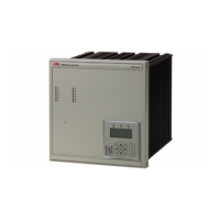
Numerical generator protection
ABB Switzerland Ltd
Utility Automation
REG316*4
1MRK502004-Ben
Page 11
Table 3: Optocoupler inputs
Table 4: Light-emitting diodes
Table 5: Configuration and settings
Table 6: Remote communication
No. of optocouplers 8, 4 or 14 acc. to I/O unit
(316DB61, 316DB62 or 316DB63)
Input voltage 18 to 36 V DC / 36 to 75 V DC / 82 to 312 V DC / 175 to 312 V DC
Threshold voltage 10 to 17 V DC / 20 to 34 V DC /40 to 65 V DC / 140 to 175 V DC
Max. input current <12 mA
Operating time 1 ms
The user can assign the inputs to protection functions.
Choice of display modes:
· Accumulates each new disturbance
· Latching with reset by next pick-up
· Latching only if protection trips with reset by next pick-up
· Signalling without latching
Colours 1 green (standby)
1 red (trip)
6 or 14 yellow (all other signals)
The user can assign the LED’s to protection functions.
Local via the communication interface on the front port connector using an IBM-compatible PC with Win-
dows NT 4.0 or Windows 2000. The operator program can also be operated by remote control via a
modem.
Operator program in English or German
RS232C interface
Data transfer rate
Protocol
Electrical/optical converter (optional)
9 pin Sub-D female
9600 Bit/s
SPA or IEC 60870-5-103
316BM61b
PCC interface
Number 2 plug-in sockets for type III cards
PCC (optional)
Interbay bus protocol
Process bus protocol
(interbay and process bus can be used concurrently)
LON or MVB (part of IEC 61375)
MVB (part of IEC 61375)
LON bus
Data transfer rate
PCC with fibre-optical port, ST connectors
1.25 MBit/s
MVB bus
Data transfer rate
PCC with redundant fibre-optical port, ST
connectors
1.5 Mbit/s
Event memory
Capacity
Time marker resolution
256 events
1 ms
Time definition without synchronizing <10 s per day
Engineering interface integrated software interface for signal
engineering with SigTOOL

 Loading...