Now the signals TRIP1 and TRIP should be activated.
6. With reduced amplitude of the injected voltage to 0.8 VBase the current amplitude
and angle is changed via ZC + (ZA – ZC)/2 to a value corresponding to half IBase
and 180° between the injected current and voltage.
This is done with a speed so that the final impedance is reached after 1s. As the
injected voltage is lower than 0.92 VBase the PICKUP signal should be activated. In
addition to this the signal ZONE2 should be activated.
7. Set N2Limit to 1 and repeat step
6.
Now the signals TRIP2 and TRIP should be activated.
IED
B A
E
B
E
A
X’
d
X
T
Z
S
Zone 1 Zone 2
jX
R
ZB
ZA
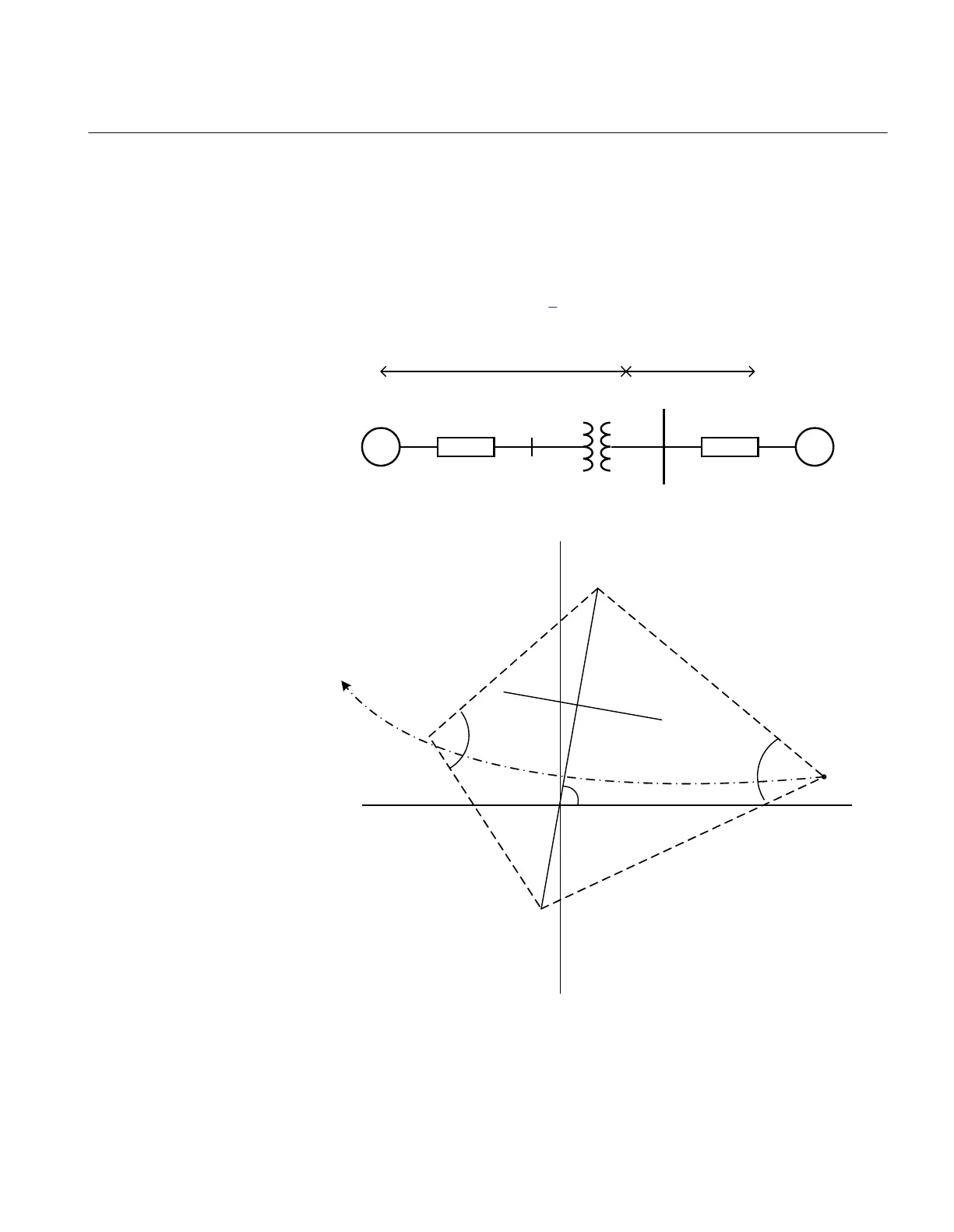
Pole slip
impedance
movement
Zone 2
Zone 1
WarnAngle
TripAngle
f
ZC
ANSI07000099_2_en.vsd
ANSI07000099 V2 EN
Figure 38: Setting of the pole slip protection PSPPPAM (78)
1MRK 504 165-UUS - Section 11
Testing functionality by secondary injection
Transformer protection RET670 2.2 ANSI 149
Commissioning manual

 Loading...


