P1
P3
P4
X
R
LineAngle
Z1Fwd
Z1Rev
P2
IEC11000312-2-en.vsd
IEC11000312 V2 EN
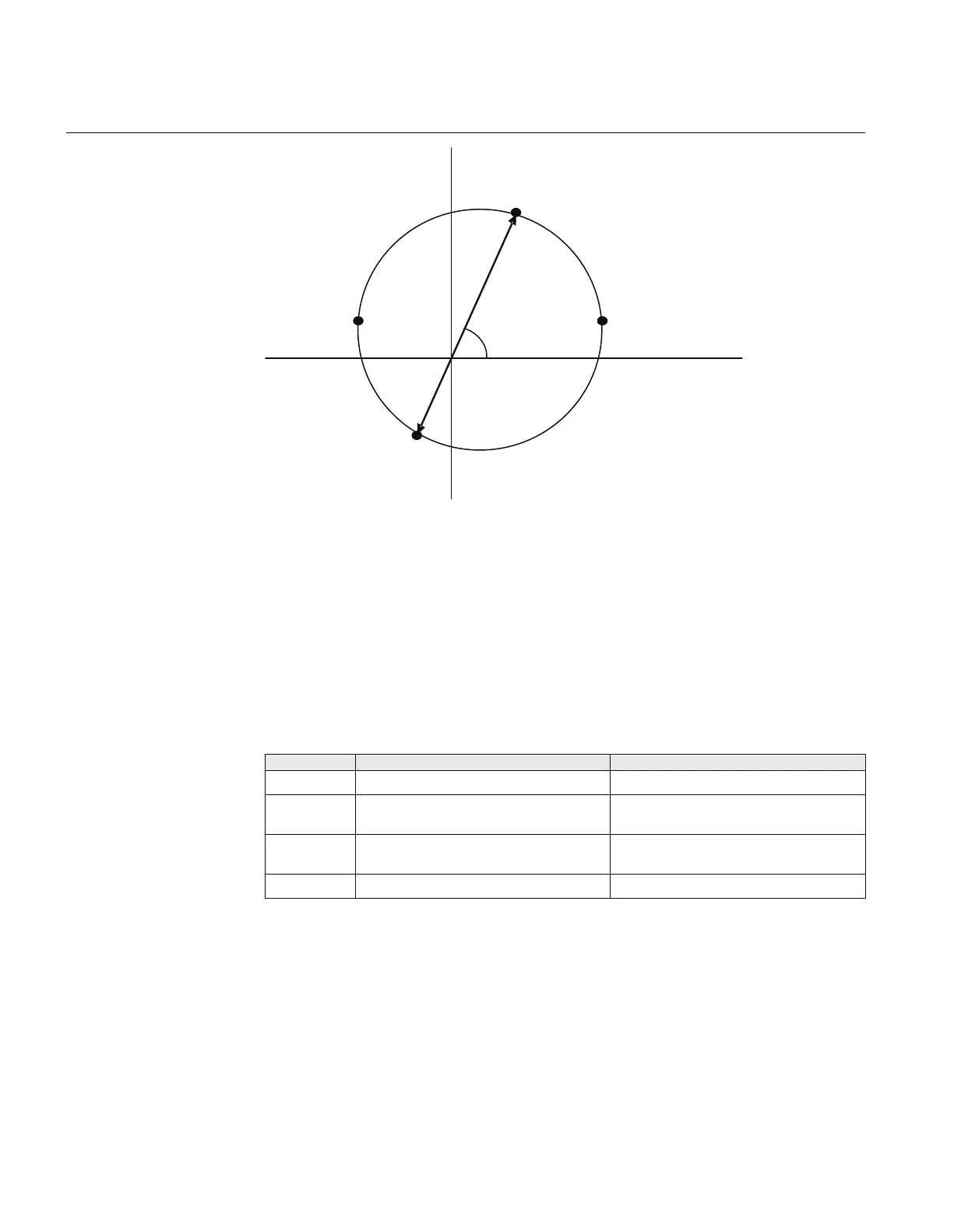
Figure 42: Proposed four test points for phase-to-phase fault
Where,
Z1Fwd
is the forward positive sequence impedance setting for zone 1
Z1Rev
is the reverse positive sequence impedance setting for zone 1
LineAngle
is the Impedance angle for phase-to-phase fault in degrees
Test points X R
P1
Z1Fwd
· sin(
LineAngle
)
Z1Fwd
· cos(
LineAngle
)
P2 ((
Z1Fwd
-
Z1Rev
/ 2) · sin(
LineAngle
))
Z1Fwd
/ 2 · (1 + cos(
LineAngle
) +
Z1Rev
/ 2
· (1 – cos(
LineAngle
))
P3 ((
Z1Fwd
-
Z1Rev
/ 2) · sin(
LineAngle
)) -
Z1Fwd
/ 2 · (1 – cos(
LineAngle
) +
Z1Rev
/ 2
· (1 + cos(
LineAngle
))
P4 -
Z1Rev
· sin
LineAngle
-
Z1Rev
· cos(
LineAngle
)
Change the magnitude and angle of phase-to-phase voltage, to achieve impedances at test
points P1, P2, P3 and P4. For each test point, observe that the output signals, PICKUP and
PU_Z1 are activated where x refers to the actual phase to be tested. After the trip time
delay for the zone 1 has elapsed, the signals TRIP and TRZ1 shall be activated.
Section 11 1MRK 504 165-UUS -
Testing functionality by secondary injection
174 Transformer protection RET670 2.2 ANSI
Commissioning manual

 Loading...


