To verify zone 2 and zone 3 mho characteristic, at least two points must be tested. The
default measuring loop selected is maximum current phase to current loop. Hence the
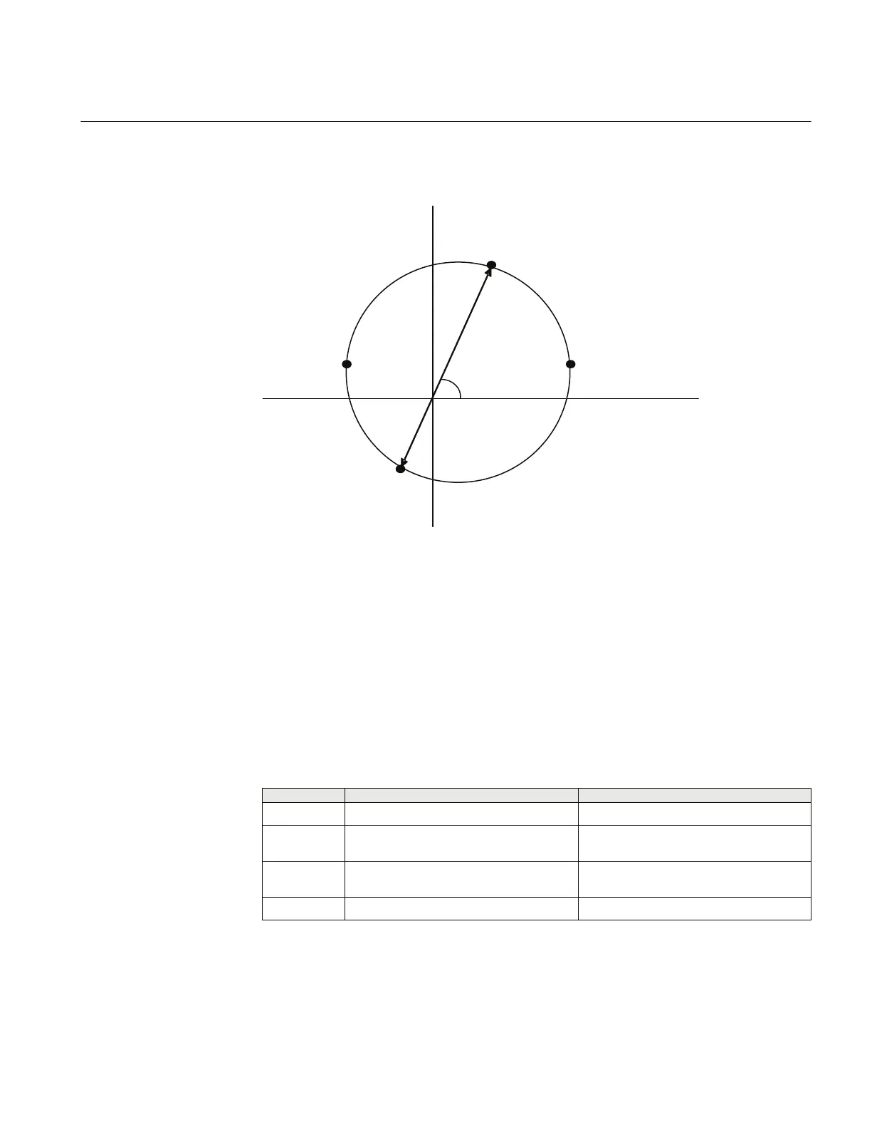
below characteristics are tested with phase–to-ground fault conditions.
P1
P3
P4
X
R
LineAngle
ZxFwd
ZxRev
P2
IEC11000313-1-en.vsd
IEC11000313 V2 EN
Figure 43: Proposed four test points for phase-to-earth fault
Where,
ZxFwd
is the forward positive sequence impedance setting for zone x (where, x is 2- 3
depending on the zone selected)
ZxRev
is the reverse positive sequence impedance setting for zone x (where x is 2- 3
depending on the zone selected)
LineAngle
is the Impedance angle for phase-to-phase fault in degrees
Test points X R
P1
ZxFwd
· sin(
LineAngle
)
ZxFwd
· cos(
LineAngle
)
P2 ((
ZxFwd
-
ZxRev
/ 2) · sin(
LineAngle
))
ZxFwd
/ 2 · (1 + cos(
LineAngle
) +
ZxRev
/2 ·
(1 – cos(
LineAngle
))
P3 ((
ZxFwd
-
ZxRev
/ 2) · sin(
LineAngle
)) -
ZxFwd
/ 2 · (1 – cos(
LineAngle
) +
ZxRev
/ 2
· (1 + cos(
LineAngle
))
P4 -
ZxRev
· sin(
LineAngle
) -
ZxRev
· cos(
LineAngle
)
1MRK 504 165-UUS - Section 11
Testing functionality by secondary injection
Transformer protection RET670 2.2 ANSI 175
Commissioning manual

 Loading...


