19 of 24
Jun 2001
Detectors
Agilent 6890 Gas Chromatograph Service Manual
Flame Ionization Detector (FID) 310
Replacement procedures
6. Secure the manifold in place using the Torx T-20 screw. See
Figure 310-13.
7. Route the gas tubing behind the manifold, over the top of the chassis, and
through the slots as shown in Figure 310-15.
8. Connect the ribbon cable to the mating connector on the pneumatics
board. Arrange the cable to keep it away from the valves and keep it from
being pinched against the manifold.
For the back detector, you may want to loosen the manifold and slide it
out of the carrier a few centimeters to connect the cable to the pneumatics
board. Then, reinstall the manifold.
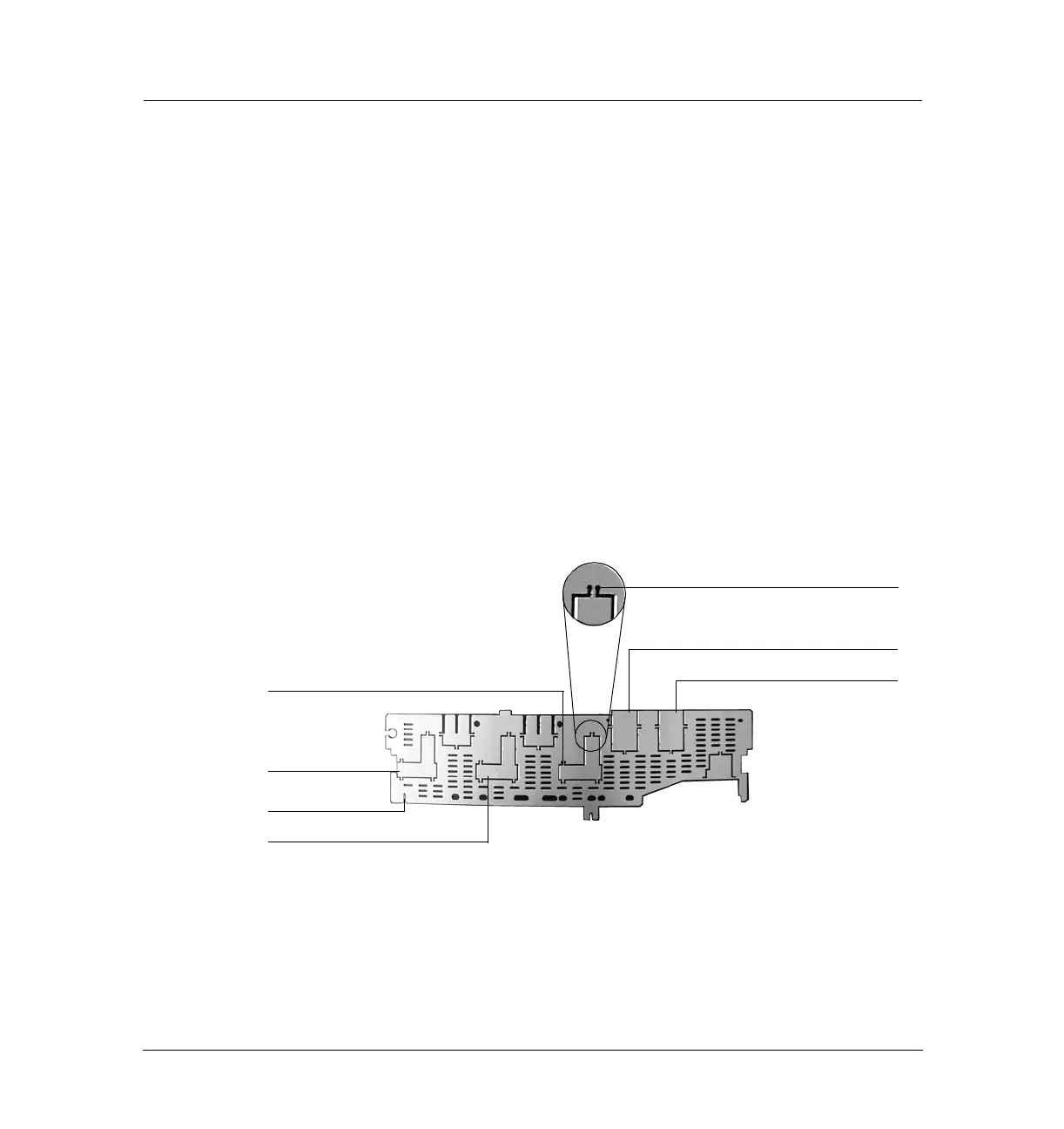
9. Using a pair of needle-nosed pliers, remove the appropriate top rear panel
detector cutout for the FID. Also remove any cutouts needed to access
other manifolds or accessories installed in the GC. See Figure 310-16.
Figure 310-16 Top rear panel cutouts
10. Place the new top rear panel on its left-most mounting screw. Use the
screw as a hinge and angle the panel while sliding each manifold tag
through its cutout in the panel, working from left to right. When all the
tags are through the panel, finish installing the panel on the GC.
Insert tip of
pliers here
Front detector
Back detector
Front inlet
Back inlet
Auxiliary
Left most screw slot
 Loading...


