360 Auxiliary EPC
Replacement procedures
10 of 16
Jun 2001
Detectors
Agilent 6890 Gas Chromatograph Service Manual
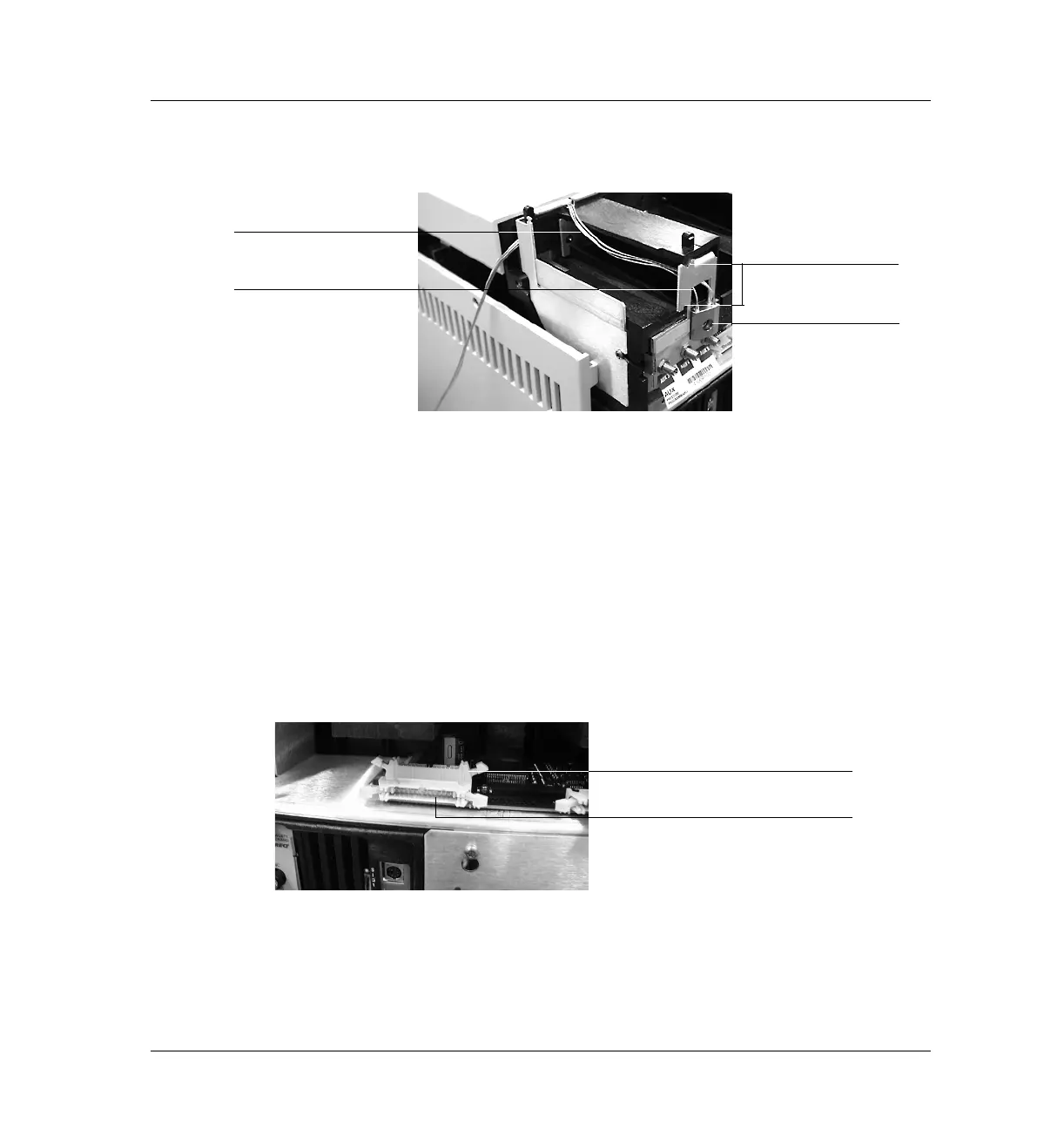
Figure 360-6 Manifold, after installation
8. Route the gas tubing behind the manifold, over the top of the chassis, and
through the slots as shown in Figure 360-2 and Figure 360-6.
9. Connect the ribbon cable to the mating connector on the pneumatics
board. This is behind the connector for the back detector and faces up.
See Figure 360-7.
10. Secure the manifold in place using the Torx T-20 mounting screw. See
Figure 360-2.
Figure 360-7 Auxiliary and back detector connectors
11. If the detector cable is in the way, remove it temporarily while you connect
the Aux cable. Arrange the cable to keep it away from the valves and keep
it from being pinched against the manifold.
Attach gang fitting
Bracket is flush with
Route tubing along
carrier rails
Check for interference
this path
Connector for auxiliary manifold
Connector for back detector manifold
 Loading...


