430 Power/Electronics Replacement
Installing an MIO card (6890A and 6890 Plus)
8 of 26
Jun 2001
Mainframe
Agilent 6890 Gas Chromatograph Service Manual
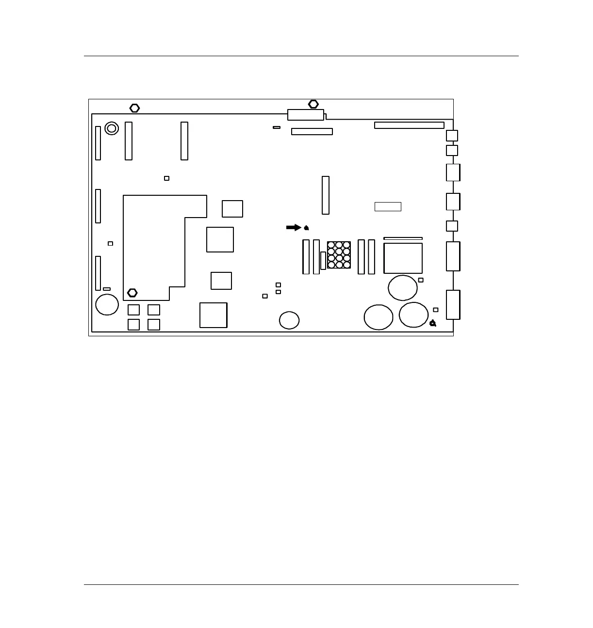
Figure 430-6 Location for MIO bracket standoff
4. Screw the hexagonal metal standoff provided with the MIO kit into the
hole vacated by the T-10 screw. Use a 3/16-inch nut driver to tighten the
standoff 1⁄ 8 turn past finger-tight.
5. Route the oven sensor wires (P16) and the main power wire harness (J7)
underneath the standoff.
6. Plug the jumper board from the MIO kit into the P15 socket on the main
board. Make sure the P7 connector on the jumper card points toward the
back of the instrument.
7. From the back of the instrument, insert the metal bracket into the MIO
card slot.
Hole for
transformer
Oven Access
Cutout
Beeper
P11 P1
P2
P12
P13
P17
GND
P15
DSP
Gate
Array
CPU
GND
4 ROM
Sockets
3V
Lithium
battery
Gate
Array
P16
P21
P22
P3
J1
J2
JP1
JP2
J4
J6
J5
F2
F1
F4 F3
P18
+24V
–24V
+15V
–15V
+5v
Capacitor
Capacitors
cable
J8
 Loading...


