1010 Cabling Diagrams, 6890A and 6890 Plus
6890 GC GC Automatic Liquid Sampler Non-Agilent Data System
4 of 14
Jun 2001
Cabling Configuration and Electronics
Agilent 6890 Gas Chromatograph Service Manual
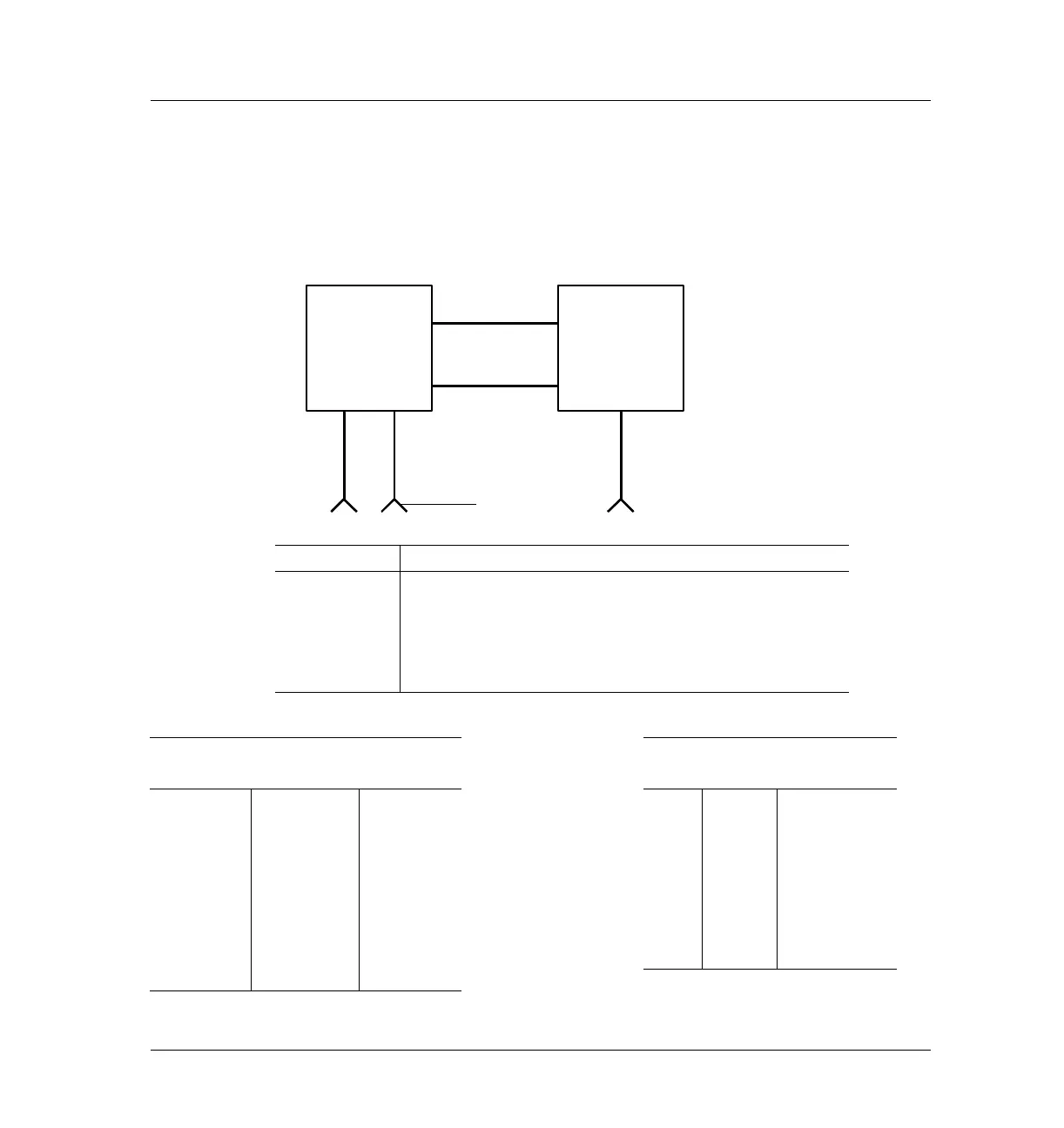
6890 GC
GC Automatic Liquid Sampler
Non-Agilent Data System
Figure 1010-4
Number Part no. and description
1 G1530-60600, 2-m RS-232 cable, 9-pin female/9-pin female
2 G1530-60930, 2-m APG remote cable, 9-pin male/9-pin male
3 35900-60670, General use APG remote cable, 9-pin male/spade lug
4 G1530-60590, External event cable, 8-pin/spade lugs
5 G1530-60630, General purpose BCD cable
35900-60670 APG remote
cable spade lug identification
G1530-60590 External event
cable spade lug identification
Connect 1
9pin
(male)
Signal name
Connector 2
spade lugs
Pin Color Signal
1 GND Black 1 Yellow 24 V Out 1
2 Prepare White 2 Black 24 V Out 2
3 Start Red 3 Red Ground
4 Shut down Green 4 White Ground
5 Reserved Brown 5 Orange Contact 1
6 Power on Blue 6 Green Contact 1
7 Ready Orange 7 Brown Contact 2
8 Stop Yellow 8 Blue Contact 2
9 Start Request Violet
6890 GC
ALS
1 RS-232
3 APG remote
4 External event
5 BCD cable
Spade lug
termination
The 7683 ALS
controller is internal to
the 6890 Plus GC.
The G2613A injector
and G2614A tray
plug into the GC.
2 APG remote
 Loading...


