7-18
Adjustments
Manual Adjustments
Predistortion and Detector Offset (8648B/C/D Only)
(Some versions of hardware do no have the following potentiometers. Do not run this
adjustment if the potentiometers are not present.)
Description
This adjustment sets up the Detector Offset potentiometer on the A10 frequency extension
board and the Predistortion potentiometer on the A6 output board while measuring the
power at the RF Output connector. With the DUT set to 100 MHz, the Detector Offset
potentiometer is adjusted for −10 dBm reading at the RF output. Then, the Predistortion
potentiometer is adjusted for −17.5 dBm at the RF output. These two adjustments are
iterated between until both power levels are within 0.1 dBm of their respective power
levels. The DUT is set to 1.5 MHz and the predistortion potentiometer is adjusted for
−17.0 dBm.
Required Test Equipment
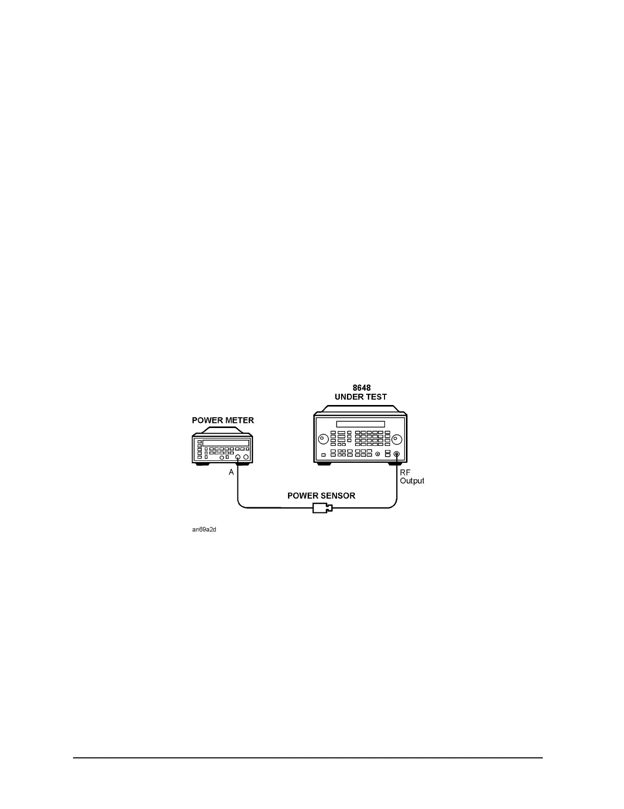
• Power Meter
• Power Sensor
Procedure
Figure 7-17. Predistortion and Detector Offset Test Setup
1. Connect the equipment as shown above.
2. Preset all of the equipment.
3. Follow the instructions as they are displayed on the PC.

 Loading...


