14 Agilent 1260 Infinity RID User Manual
1 Introduction to the Refractive Index Detector
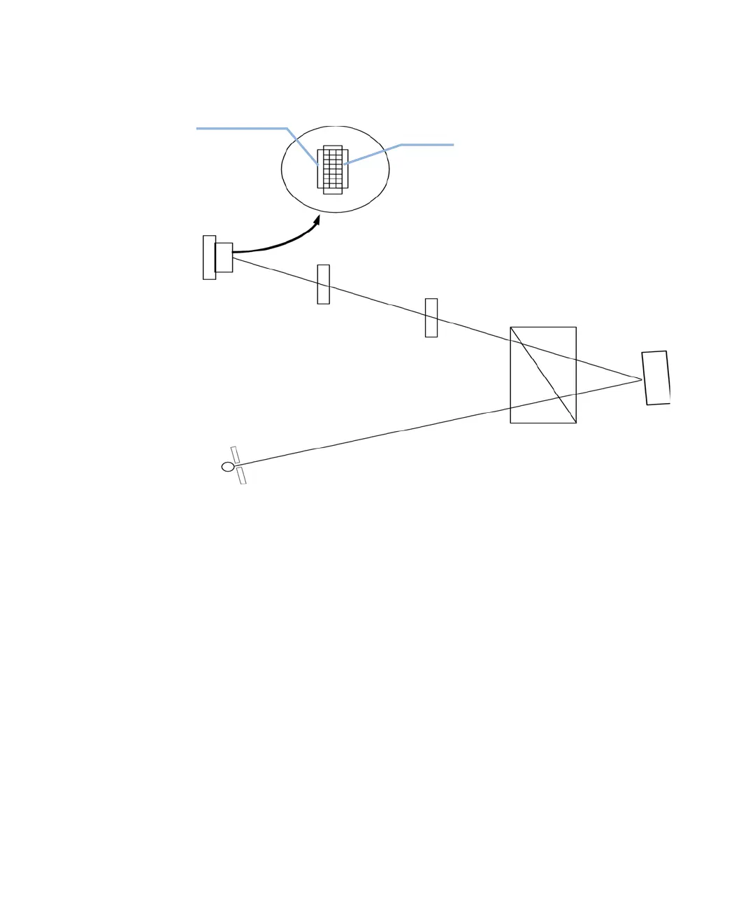
Detection Principle
Figure 3 Detection Principle
Measurements
Initially both sample and reference cell are flushed with mobile phase. The
reference cell is then closed and solvent flows only through the sample cell.
The refractive index of the mobile phase in both cells is the same and the
position of the zero glass can be adjusted so that the detector is in optical
balance with an equal amount of light falls on each diode.
When sample elutes from the column into the sample cell the refractive index
of the cell contents changes. The change in refractive index deflects the light
beam as it passes through the flow cell resulting in an unequal amount of light
falling on each diode. The change in current from the diodes that this causes is
amplified and used to produce the calibrated detector signal. This signal
expressed, as nano Refractive Index Units (nRIU), corresponds to the
difference between the refractive index of sample in the sample cell and the
mobile phase in the reference cell.
OZgd\aVhh
GZ[ZgZcXZXZaa
B^ggdg
HVbeaZXZaa
9^dYZ&
9^dYZ'
Ha^i
A^\]igZXZ^kZg