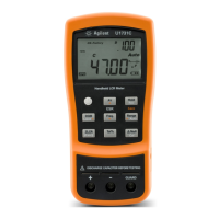
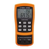
U1731C/U1732C/U1733C User’s Guide XVII
List of Tables
Tab l e 1- 1 Battery level indicator 5
Tab l e 1- 2 Power-on options 10
Tab l e 1- 3 Front panel parts 13
Tab l e 1- 4 Rear panel parts 14
Tab l e 1- 5 Keypad functions 15
Tab l e 1- 6 General annunciators 18
Tab l e 1- 7 Measurement units display 21
Tab l e 1- 8 Input terminal/socket connections 22
Tab l e 2- 1 Auto identification phase angle rules 27
Tab l e 2- 2 Auto identification series/parallel rules for resistance
measurements 27
Tab l e 2- 3 Auto identification series/parallel rules for capacitance
measurements 28
Tab l e 2- 4 Auto identification series/parallel rules for inductance
measurements 28
Tab l e 2- 5 Available test frequencies 37
Tab l e 2- 6 Factory default high and low limit values 42
Tab l e 3- 1 Setup menu key functions 52
Tab l e 3- 2 Setup menu item descriptions 54
Tab l e 3- 3 Auto identification phase angle rules 63
Tab l e 3- 4 Default user high/low limit values 66
Tab l e 4- 1 Impedance/Resistance/DCR specifications 78
Tab l e 4- 2 Capacitance specifications 79
Tab l e 4- 3 Inductance specifications 80
Tab l e 4- 4 Phase angle of impedance specifications 81
Tab l e 4- 5 Dissipation/Quality factor specifications 82
Tab l e 4- 6 Test signal specifications 83
Tab l e 4- 7 Source impedance of impedance/resistance
measurement 84
Tab l e 4- 8 Source impedance of capacitance measurement 85
Tab l e 4- 9 Source impedance of inductance measurement 86
Tab l e 5 U1782B SMD tweezers electrical characteristics 88

 Loading...


