34
5. Installation
5.10 High pressure hoses and cables
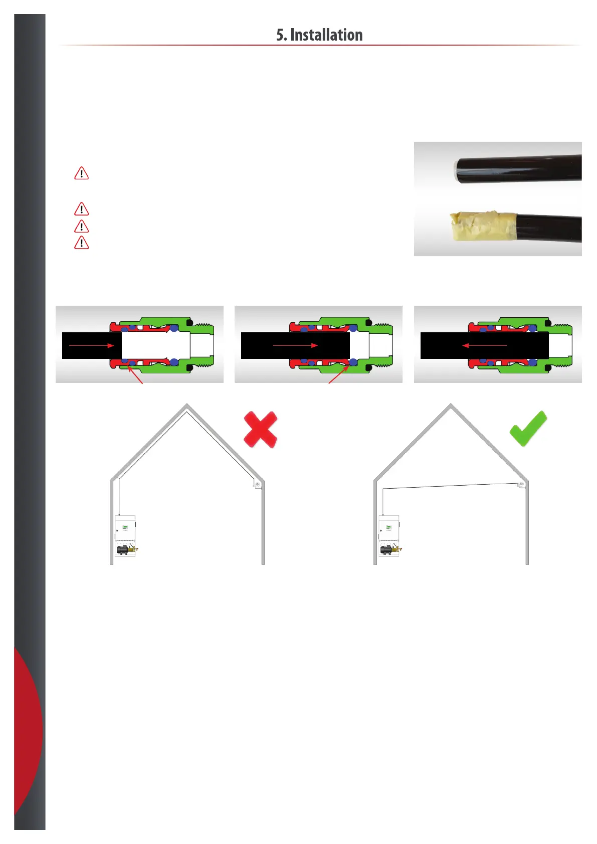
• Seal the end of the hose with tape or a plug during the installation process to prevent dirt and dust to get
inside during installation.
•
Only use “light sticky tape“ e.g. painttape, that don’t leave a glue ect. when removing it again.
• Follow datasheet for hose recommended and maximum length.
•
Do not scratch the hose on sharp edges
•
Do not bend the hose more than minimum bending radius. (see datasheet)
•
Remember to do pull test at each hose connection to our sliplock ttings. See gur 3.
(if the tting dosn’t grip the hose rst time, change the tting)
• Avoid high loops ” air traps ” between HydroSens and nozzles. See gur 4.
• Ensure that cable tray or routing are following locale rules and are not mixed with building installation.
Plug
Tape
Figur 1. Push thru 1
st
O-ring
Figur 2. Push thru 2
nd
O-ring
Figur 3. Pull test
High pressure hose
Installations- and sensor cable
• Cable feed between control, sensor, atomizers or any other cables that is a part of the machine installation must be done to meet directives, and locale regulations
• Our mashine installation is not to be mixed with cable for building or permanent installation in the cable trays
• Installation should be done in a way, that makes it possible to work with the machinery without getting in contact with other installations
• Remember to leave extra cable for the sensor to be able to reposition the sensor during startup / nal adjustment
• ΔU% voltage drop has to be calculated to the individual installation length and load, cable type
• Overload protection as CE marked
• Shortcircuit also as CE marked.
Figur 4. Figur 5.
201218