37
5. Installation
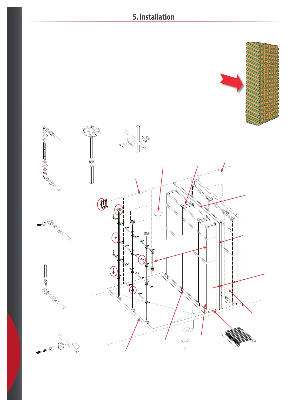
5.13 AHU
• Position the nozzle rack in safe distance from “non wet area“ to avoid turbulence causing water outside the humidication chamber.
• Start by lining the nozzle up as illustrated in the order conrmation. adjustment can be done during startup commissioning if needed.
• Ensure that the both rack and nozzles can be maintained through inspection door in a safe way.
• Position the duct sensor in safe distance after the wet chamber. Considerinig air velocity, there can be super ne water aerosols that
may cause sensor mis readings.
• Room sensor should be position in exhaust air.
• Position the bulkhead behind the rack, to avoid hoses in front of the nozzles.
Min. 20 mm
A - Bulkhead B - Foot
Inspection door
- Not incl.
Light
- Not incl.
Seperator
Droplet seperator
- Option
Seperator restraints
- Not incl.
Blanking plate
- Not incl.
Seperator restraints
- Not incl.
Seperator support channel
- Not incl.
Drainer
- Not incl.
Seperator xing angle
- Not incl.
Recomended
500 - 1000 mm
at 1 - 3 m/s
Inspection door
- Not incl.
C - End nozzle
D - Water inlet
E - Nozzle bracket S
F - Rack bracket S
Air ow
Top
A
C
B
D
E
F
201218