179
TROUBLESHOOTING
[Engine Coolant System]
[Refrigerant system]
Ignition coils 1 ~ 4 (IG1 ~ 4)
(IG4 is 15 TON only)
1; CN8[1]-[3] White-Black
2; CN8[2]-[3] Yellow-Black
3; CN8[7]-[3] Blue-Black
4; CN8[8]-[3] Brown-Black
13~15 VDC
Primary resistance value
(68 ℉ 20( ℃ ))
8 TON 2.8 Ω
15 TON 1.85 Ω
Igniter (IGN) Coil connector section 0-12 Vpulse wave ※Do
not measure with a circuit
tester
Engine oil pan heater
(E/G OPH)
(Unit with drain heater kit
only)
Cold district PCB
200 V AC 833 Ω
CN3[2]-[5] White-White
Exhaust water drain heater
(DH)
(Unit with drain heater kit
only)
Cold district PCB
CN3[1]-[4] Yellow-Yellow
200 V AC
Refer to table below
(Resistance of exhaust water
drain heater)
NOTE) When measuring resis-
tance at the connector on
the PCB, measured value is
combined value because
following 2 heaters are
connected to one connector
in parallel.
Exhaust water drain filter
heater
Exhaust water drain hose
heater
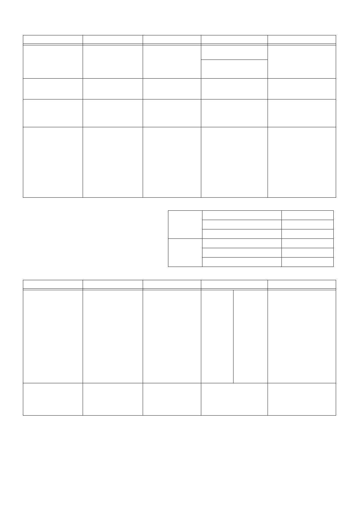
Inspection item Measurement point Normal voltage (V) Normal resistance value (Ω)Remark
(Resistance of exhaust water drain heater)
8 TON
On the PCB (combined value) 421 Ω
Drain filter 833 Ω
Drain hose 851 Ω
15 TON
On the PCB (combined value) 476 Ω
Drain filter 667 Ω
Drain hose 1667 Ω
Inspection item Measurement point Normal voltage (V) Normal resistance value (Ω)Remark
Engine coolant temperature
sensor (WT)
CN6[11]-[12] Black-Black Temperature
( ℉ ( ℃ ))
Resistance
(Ω)
• Disconnection temperature is
detected (lower than 32 ℉
(0
℃ )).
Disconnection is detected for
3 minutes during engine oper-
ation. (engine coolant temper-
ature sensor disconnection→
70-0)
• Short circuit temperature is
detected (248 ℉ (120 ℃ )).
Shot circuit is detected for
1 minute (engine coolant
temperature sensor short
circuit→80-1)
122 (50) 17.6 k
176 (80) 6.1 k
212 (100) 3.3 k
230 (110) 2.5 k
Engine coolant pump (WP) DCBL PCB ; CN9
[3]-[2] Black-White
[2]-[1] White-Red
[3]-[1] Black-Red
[Pseudo sine wave]
Maximum output 160 V AC
[effective value]
(130 V AC [absolute
average])
8 TON 16 ~ 25 Ω
15 TON 10 ~ 18 Ω
 Loading...