28
Introduction
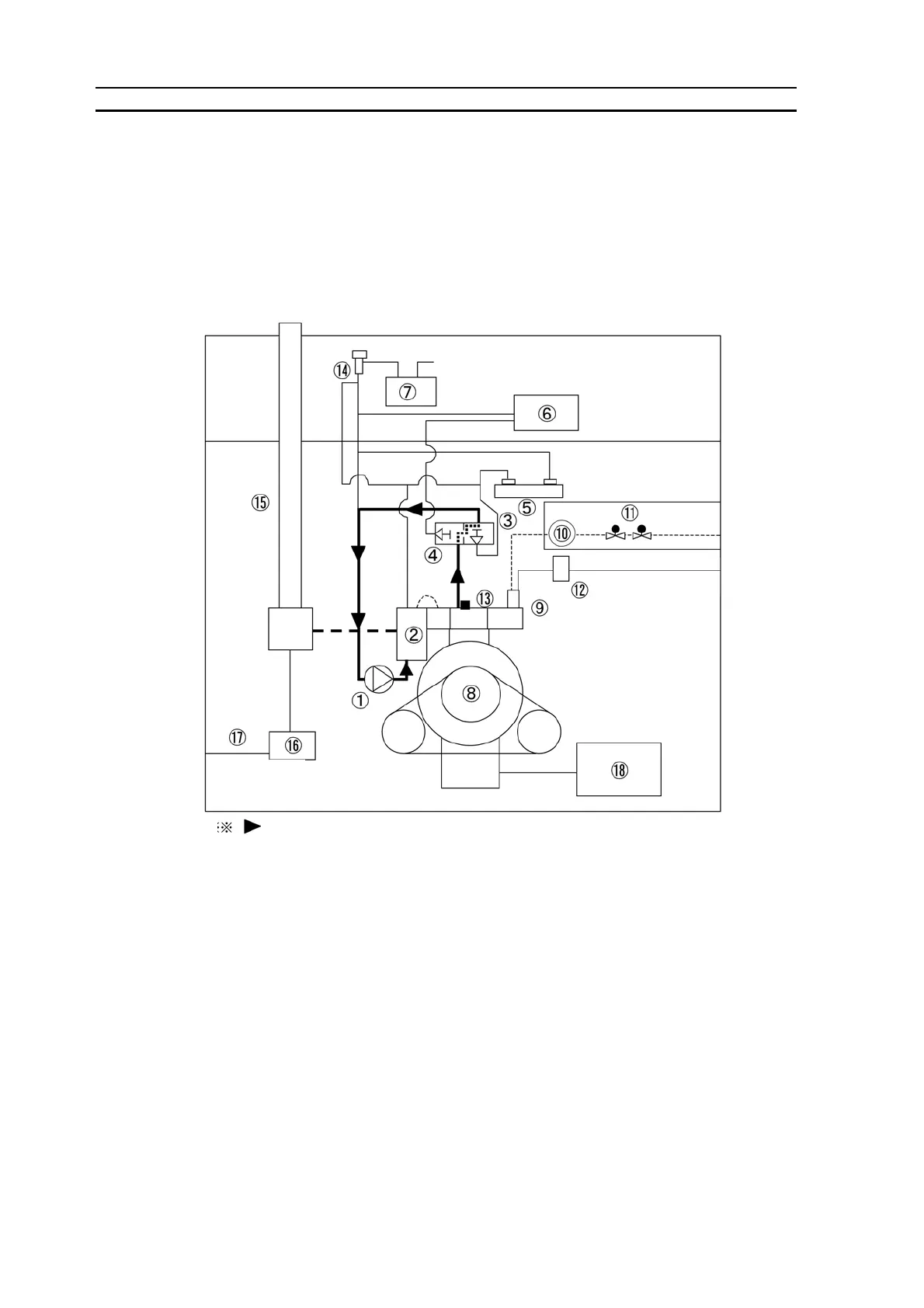
2) Engine Coolant / Fuel Gas / Intake Air and Exhaust Air System Diagrams
1. 8 TON
Engine coolant · · · a) When the engine coolant temperature is 140 ℉ (60 ℃ ) or lower
Engine coolant sent from the engine coolant pump ( ① ) is heated throuth the exhaust air
heat exchanger ( ② ) and the engine ( ⑧ ). The heated engine coolant returns to the engine
coolant pump ( ① ) by making a shortcut via the thermostat ( ④ , ③ ).
① : Engine coolant pump ⑦ : Engine coolant reserve tank ⑬ : Engine coolant temperature sensor
② : Exhaust air heat exchanger ⑧ : Engine ⑭ : Radiator cap
③ : Thermostat (140 ℉ (60 ℃ ) ⑨ : Gas mixer ⑮ : Exhaust air pipe
④ : Thermostat (158 ℉ (70 ℃ ) ⑩ : Gas regulator ⑯ : Exhaust water drain filter
⑤ : Sub heat exchanger ⑪ : Electromagnetic gas valve ⑰ : Exhaust water drain hose
⑥ : Radiator ⑫ : Air filter ⑱ : Sub oil reservoir
shows the coolant flow direction
 Loading...