233
TROUBLESHOOTING
5. Board Maintenance Functions
1) Outline of the Maintenance Function
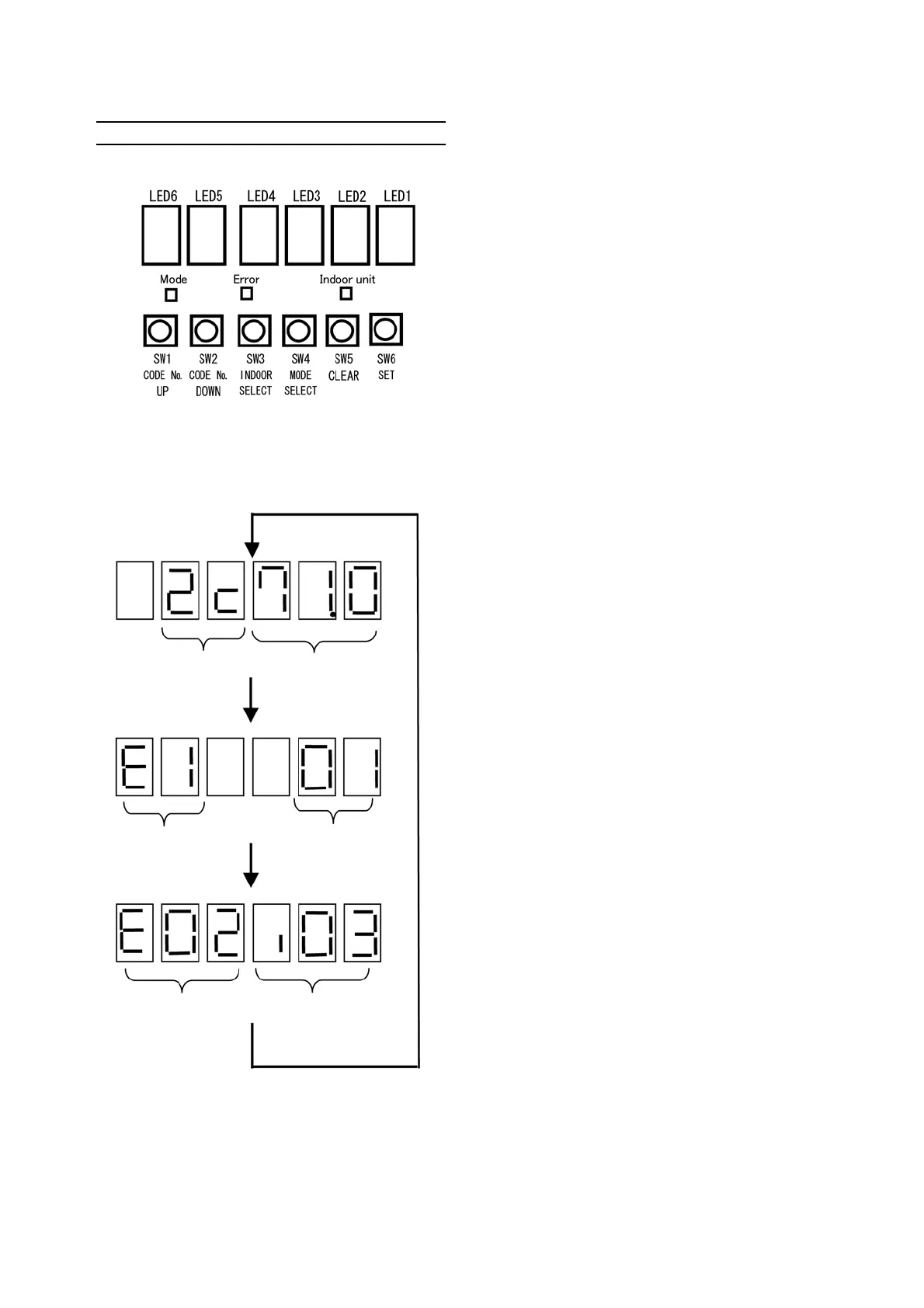
Arrangement of the LEDs and buttons for board maintenance functions
Display after turning the power ON
After turning the power ON, the display is switched "Model type/Capacity" → "Model code/Main software
version" → "Engine software version" as follows.
LED display is assigned as follows unless otherwise stated.
LED 1 ~ 4: Data display.
LED 5 ~ 6: Code number display (code No.00 ~ E7)
Alternate display of code number and indoor
unit number (code No.E8 ~ FF)
※ Model type
LED 5: Model series
2: 15 TON (3Y engine model)
1: 8 TON (950P engine model)
LED 4: Indoor unit connection scheme
C: Multi type
※ Outdoor unit capacity
45.0 : 8 TON
71.0 : 15 TON
※ When approximately 10 seconds have passed,
the display proceeds to running hours display
mode.
Model type
Outdoor unit capacity
Model code
Main software version
Engine software
version
I/F software
version
1 second
1 second
1 second
 Loading...