203
TROUBLESHOOTING
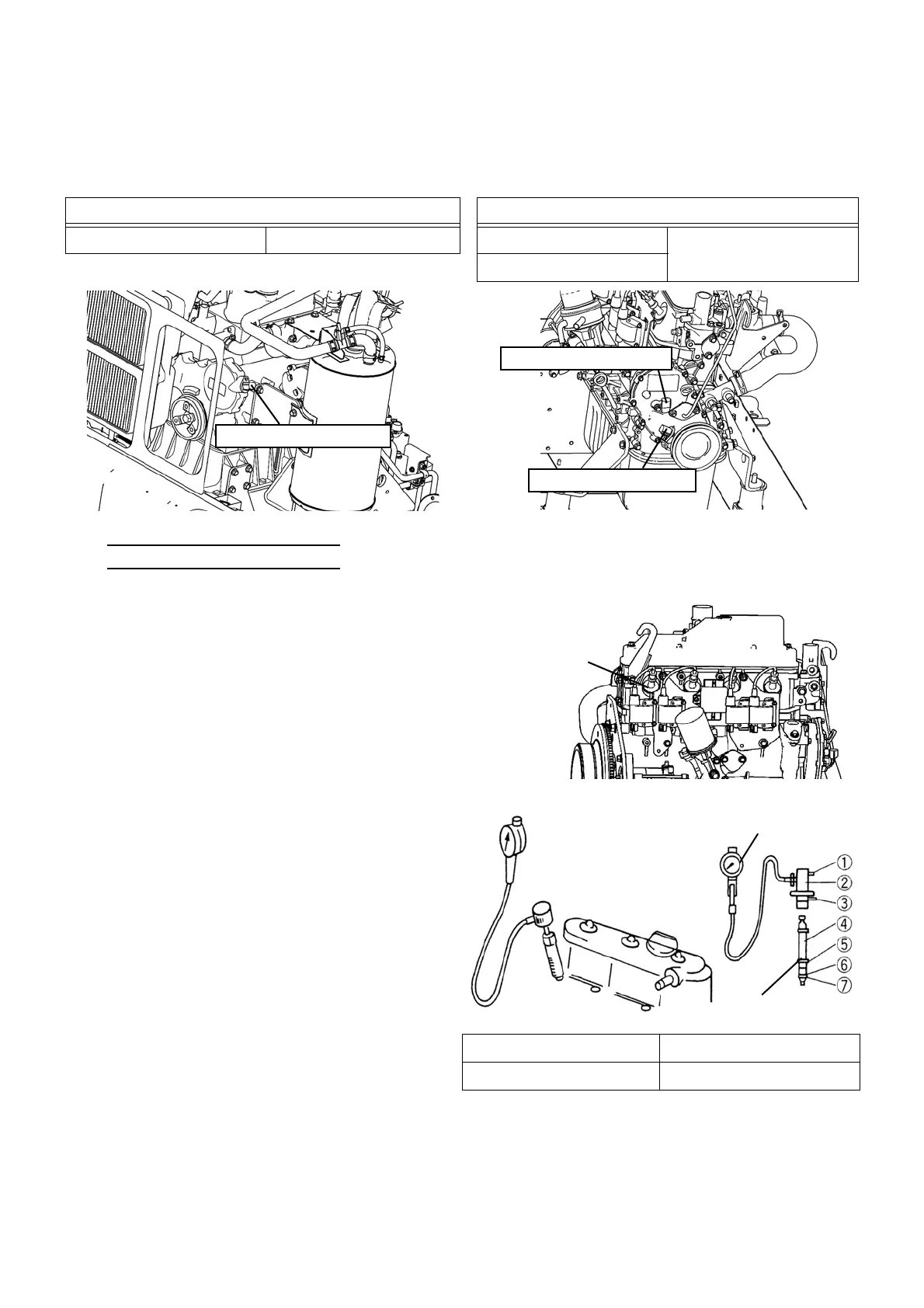
3. Inspect engine speed sensor
1) Turn OFF the electric leakage breaker.
2) Measure the resistance value between both terminals of the engine speed sensor.
13) Compression Inspection
8. Select "Actuators output condition/individual actuating (code No. 20)" in the check mode of the board mainte-
nance functions. Turn ON "Main side output permission", "Engine side output permission", "Starter transform-
er", and "Starter" in order so that the starter can operate for 5 seconds to crank the engine, and measure the
compression.
9. Push part ① to reset the gauge to "zero". Repeat the above procedure for other cylinders.
[ 8 TON ] [ 15 TON ]
Standard resistance value (68 ℉ (20 ℃ )) Standard resistance value (68 ℉ (20 ℃ ))
Engine speed sensor G2 1,100 ± 150 Ω Engine speed sensor G2
1,100 ± 150 Ω
Engine speed sensor Ne
Engine speed sensor G2
Engine speed sensor G2
Engine speed sensor Ne
Measure the compression of each engine cylinder with a
compression gauge to assure correct engine output.
1. Close the fuel gas valve.
2. Pull the caps to remove the cables.
NOTE) Do not pull the cable.
3. Remove the spark plugs with a plug wrench.
Cap
4. Insert part ⑤ of the adapter into the plug hole and
tighten it.
5. Attach part ③ of the compression gauge to part ④
of the adapter and turn part ③ in the direction indi-
cated by arrow until the turning effort becomes
heavy. The rubber portion of part ⑤ is firmly
pressed against the plug hole and thus fixed tightly.
6. Select "Engine throttle valve open position (code
No. 15)" in the check mode of the board mainte-
nance functions. Then set the engine throttle valve
to 500-step position (fully opened position).
7. Install the compression gauge at a safe location
apart from moving parts.
Pressure standard value 203 psi (1.4 MPa) or higher
Limit pressure 160 psi (1.1 MPa)
Compression gauge
Adapter
 Loading...