150
CONTROL
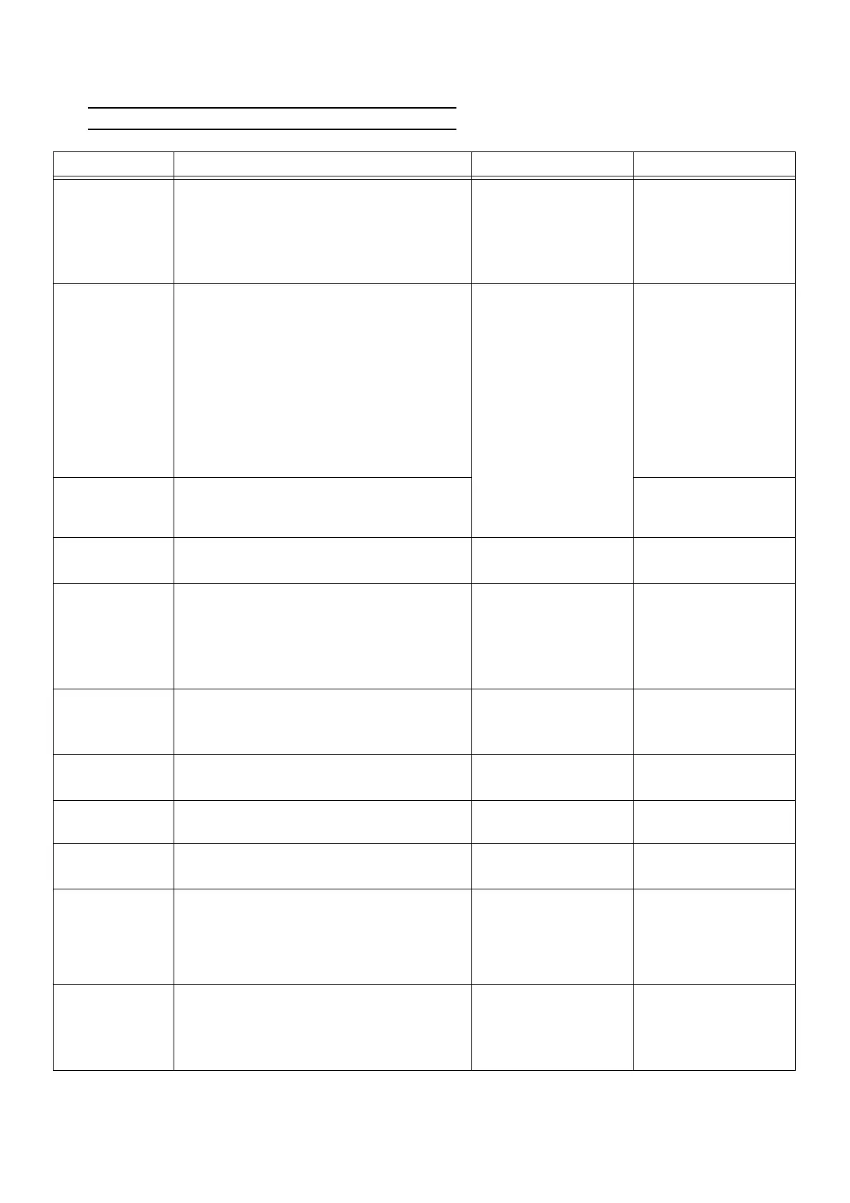
4. System Input/Output Specifications
1) Outdoor Unit Input / Output Specifications
Name Functions Specifications Connector No.
Outdoor fan
motor
Heat exchange of refrigerant and cooling the
engine coolant
Rated: 280 V DC
DC brushless
DCBL PCB FM1:
CN7[1]-[2]-[3] CN10[1]-
[2]-[3]-[4]-[5] FM2:
CN8[1]-[2]-[4] CN12[1]-
[2]-[3]-[4]-[5]
Outside air tem-
perature sensor
1. Judgement of ambient themperature under
which the system operation is prohibited
Cooling operation is prohibited at lower
than 14 ℉ (-10 ℃ )
Cooling operation is stopped at lower
than 10 ℉ (-12 ℃ )
2. Full-open control for the electronic expan-
sion valve of the stopped indoor unit
3. Outdoor fan air volume control
4. Detection of disconnection or short circuit
Refer to P177 and af-
ter, [Parts Character-
istics].
THO: CN6[9]-[10]
Engine compart-
ment tempera-
ture sensor
1. Compressor heater control
2. Detection of disconnection or short circuit
E/G R: CN6[13]-[14]
Throttle valve Control of the engine speed Rated: 12 V DC
STM: CN6[16]-[18]-
[19]-[21]-[15]-[17]
Engine oil
pressure switch
1. Judgment of abnormal oil pressure
2. Detection of disconnection in the engine oil
pressure switch
Rated: 12 V DC
Circuit OFF:
14.5 psi (0.1 MPa)
Circuit ON:
5.8 psi (0.04 MPa)
OLP: CN6[3]-[4]
Oil level switch Judgment of oil leakage
Rated: 12 V DC
Normal : ON
Error : OFF
OIL-LVL: CN4[5]-[6]
Electromagnetic
gas valve
To supply or shut off the fuel gas to the
outdoor unit
Rated: 12 V DC
GV1: CN8[4]-[10]
GV2: CN8[5]-[11]
Starter
To support the engine for self-operation at
start-up
Rated: 12 V DC -
Fuel gas flow
control valve
Control of air/fuel ratio Rated: 12 V DC
FUEL: CN6[20]-[22]-
[26]-[24]-[23]-[25]
Engine exhaust
air temperature
sensor
(unit with deodor-
ant kit only)
Detection of excessive rise of engine exhaust
air temperature
Refer to P177 and af-
ter, [Parts Character-
istics].
E/G E: CN6[7]-[8]
Engine speed
sensor
1. Engine speed detection
2. Detection for engine overspeed abnormal-
ity
3. Detection of loss of engine speed control
WB(Ne)※2: CN7[3]-[4]
WB(G2): CN7[1]-[2]
NOTE) Numbers in [ ] in the "connector No." column correspond with the pin numbers shown in circles in the wiring diagram.
※1. 8 TON only
※2. 15 TON only
 Loading...