223
TROUBLESHOOTING
39) Inspect Refrigerant High Pressure Sensor
1. Check for contact failure of connectors on the main PCB
Select "Refrigerant high pressure 1 (code No. 40)" in the monitor mode of the board maintenance functions, and
check if the pressure is displayed again when you disconnect and connect the refrigerant high pressure sensor
connector of CN4 on the main PCB.
Repair if there is a contact failure.
2. Check for power supply voltage for the refrigerant high pressure sensor
Check power supply voltage of the refrigerant high pressure sensor at CN4[33]-[32] on the main PCB.
40) Inspect Hot Gas Bypass Valve
1. Turn OFF the electric leakage breaker.
2. Check the coil resistance for hot gas bypass valve at CN11[1]-[7] on the main PCB.
3. Select "Actuators output condition/individual actuating (code No. 20)" in the monitor mode of the board mainte-
nance functions, and check that "Hot gas bypass valve" is OFF.
4. Check that 200 V AC is not applied at CN11[1]-[7] on the main PCB.
5. Select "Actuators output condition/individual actuating (code No. 20)" in the check mode of the board mainte-
nance functions. Then turn ON "Hot gas bypass valve" to check if the hot gas bypass valve is activated.
6. Check that 200 V AC is applied at CN11[1]-[7] on the main PCB.
7. Measure the pipe temperature at outlet side of the electromagnetic gas valve of the hot gas bypass valve.
The temperature is a little lower than the discharge temperature in normal status.
If the valve is blocked, the temperature does not rise when the valve opens.
NOTE) When replacing the refrigerant system parts, Refer to P221, [Technical Data When Replacing the Re-
frigerant System Parts].
Standard voltage Within 5 ± 0.25 V DC
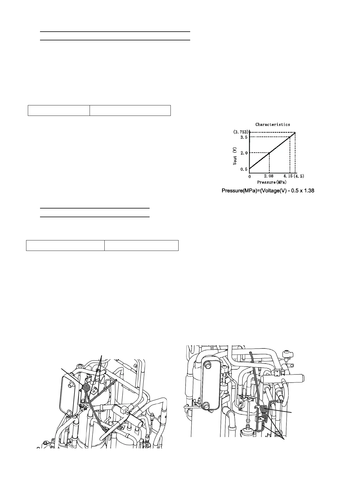
3. Check for output voltage of the refrigerant high pressure sensor
1) Measure output voltage with a tester on high-pressure sensor at
CN4[31]-[32] on the main PCB. Then refer to the figure to read the
standard pressure.
2) Make sure the valve compared with high-pressure gauge is not
much different.
NOTE) When replacing the refrigerant system parts, Refer to P221,
[Technical Data When Replacing the Refrigerant System
Parts].
Standard resistance value 1,050 Ω
[ 8 TON ] [ 15 TON ]
Coil
Hot gas bypass valves
Hot gas bypass valves
Coil
 Loading...