205
TROUBLESHOOTING
NOTE)
Do not use a feeler gauge with a blade thickness of 0.008 inch (0.2 mm) or more.When adjusting a clearance
of 0.008 inch (0.2 mm) or more, use two blades of feeler gauge.
Do not use a feeler gauge with bent or rusty blades.
When adjusting a valve clearance (while warm), set the target in the range from 0.013 inch (0.33 mm) ~ 0.015
inch (0.38 mm) (allows the insertion of a 0.013 inch (0.33 mm) blade but not a 0.015 inch (0.38 mm) blade).
15) Treatment for Compression Failure due to Carbon Deposit
[ 8 TON ]
7. Check that the intake rocker arm of No. 1 cylinder
does not move when the crank pulley is turned ap-
proximately 60˚ clockwise and counterclockwise.
(Set No. 1 cylinder to the top dead center.)
NOTE) If the intake rocker arm of No. 1 cylinder
moves, turn the crank pulley by another 1
revolution so that the top dead center marks
align with each other again.
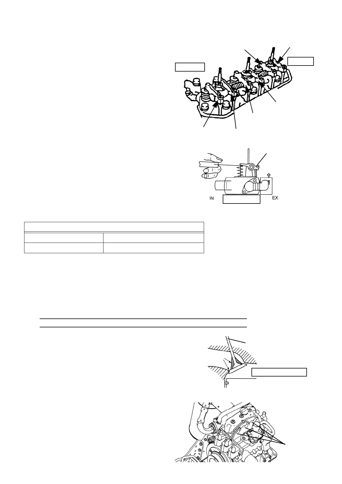
8. At the top dead center, adjust the intake valve
clearance on No. 1 and No. 3 cylinders and ex-
haust valve clearance on No. 1 and No. 2 cylinders
by loosening the adjustment nuts as shown in the
illustration.
9. Turn the crank pulley by 1 revolution by hand
so that the top dead center marks align with each
other again.
10. Adjust the intake valve clearance on No. 2 cylinder
and exhaust valve clearance on No. 3 cylinder by
loosening the adjustment nuts as shown in the
illustration.
Valve clearance standard value
When the engine is hot 0.014 ± 0.002 inch (0.35 ± 0.05 mm)
When the engine is cold 0.010 ± 0.002 inch (0.25 ± 0.05 mm)
[Rinse treatment]
When carbon deposits are formed on the valve seat
or valve and prevent the valve from sealing up the
combustion chamber, clean the valve seat or valve in
the manner explained below using a valve cleaner.
1. Close the fuel gas valve.
2. Hold and pull the cap to remove the cables
(3 places).
NOTE) Do not pull the cable.
3. Remove 3 spark plugs with a plug wrench.
No.3 exhaust
No.3 intake
No.2 exhaust
No.2 intake
No.1 exhaust
No.1 intake
Front side
Rear side
Adjustment nuts
Front side
Front side
Intake valve
Carbon
Combustion chamber
Caps
 Loading...