202
TROUBLESHOOTING
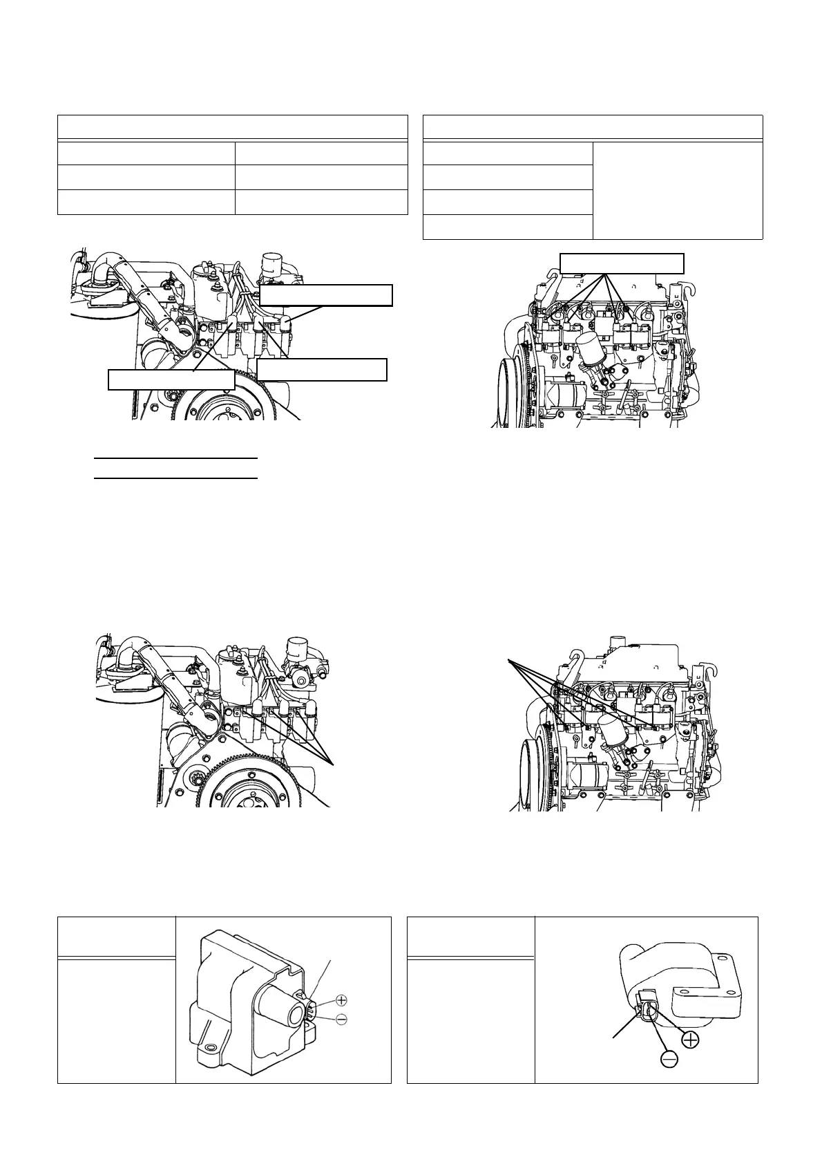
12) Inspect Igniter, etc.
1. Output voltage check of the igniter.
1) Select "Actuators output condition/individual actuating (code No. 20)" in the check mode of the board mainte-
nance functions. Then turn ON "Ignition circuit drive signal" to supply power to the igniter.
2) Disconnect the ignition coil connector, and check that 12 V DC is applied between the plus (+) terminal of the
connector and the body.
2. Inspect ignition coil
1) Turn OFF the electric leakage breaker.
2) Check that there is no disconnection or internal short circuit in the ignition coil.
[ 8 TON ] [ 15 TON ]
Standard resistance value Standard resistance value
High voltage cable #1 5.7 ± 2.2 kΩ High voltage cable #1
1.9 ~ 5.0 kΩ
High voltage cable #2 4.6 ± 1.8 kΩ High voltage cable #2
High voltage cable #3 3.5 ± 1.3 kΩ High voltage cable #3
High voltage cable #4
High voltage cable 1
High voltage cable 2
High voltage cable 3
High voltage cables
[ 8 TON ] [ 15 TON ]
Connectors
Connectors
[ 8 TON ] [ 15 TON ]
Standard
resistance value
Standard
resistance value
2.8 Ω
(68 ℉ (20 ℃ ))
1.85 Ω
(68 ℉ (20 ℃ ))
Connector
Connector
 Loading...