200
TROUBLESHOOTING
7) Operation Check of Relay
1. Check operation of starter relay (RY1)
1) Select "Actuators output condition/individual actuating (code No. 20)" in the check mode of the board mainte-
nance functions. Then check that "starter ON" is displayed.
2) Check that 12 V DC is applied at CN10[4]-[6] on the main PCB.
If 12 V DC is not applied, the output circuit of the main PCB is considered to be faulty.
3) In the same way, when the "starter" is turned ON, check that 12 V DC is applied between the [3] pin of the
starter relay (RY1) and the ground.
If 12 V DC is not applied, the starter relay (RY1) or transformer power is considered to be faulty.
[Operation of the Starter Circuit]
1) Turning the starter drive power ON
(1) After turning ON the operation switch, 200 V AC is applied from the CN11[6]-[12] on the main PCB to the
primary coil of the starter transformer.
(2) The starter drive voltage, 12 V DC, is output from the secondary terminal of the transformer and applied to
the starter transformer.
2) Driving the starter
12 V DC output from CN10 on the main PCB turns RY1 ON. This applies 12 V DC to the starter pinion coil to
activate the starter.
8) Inspect Fuel Gas Pressure
Inspect the gas presssure of fuel gas.
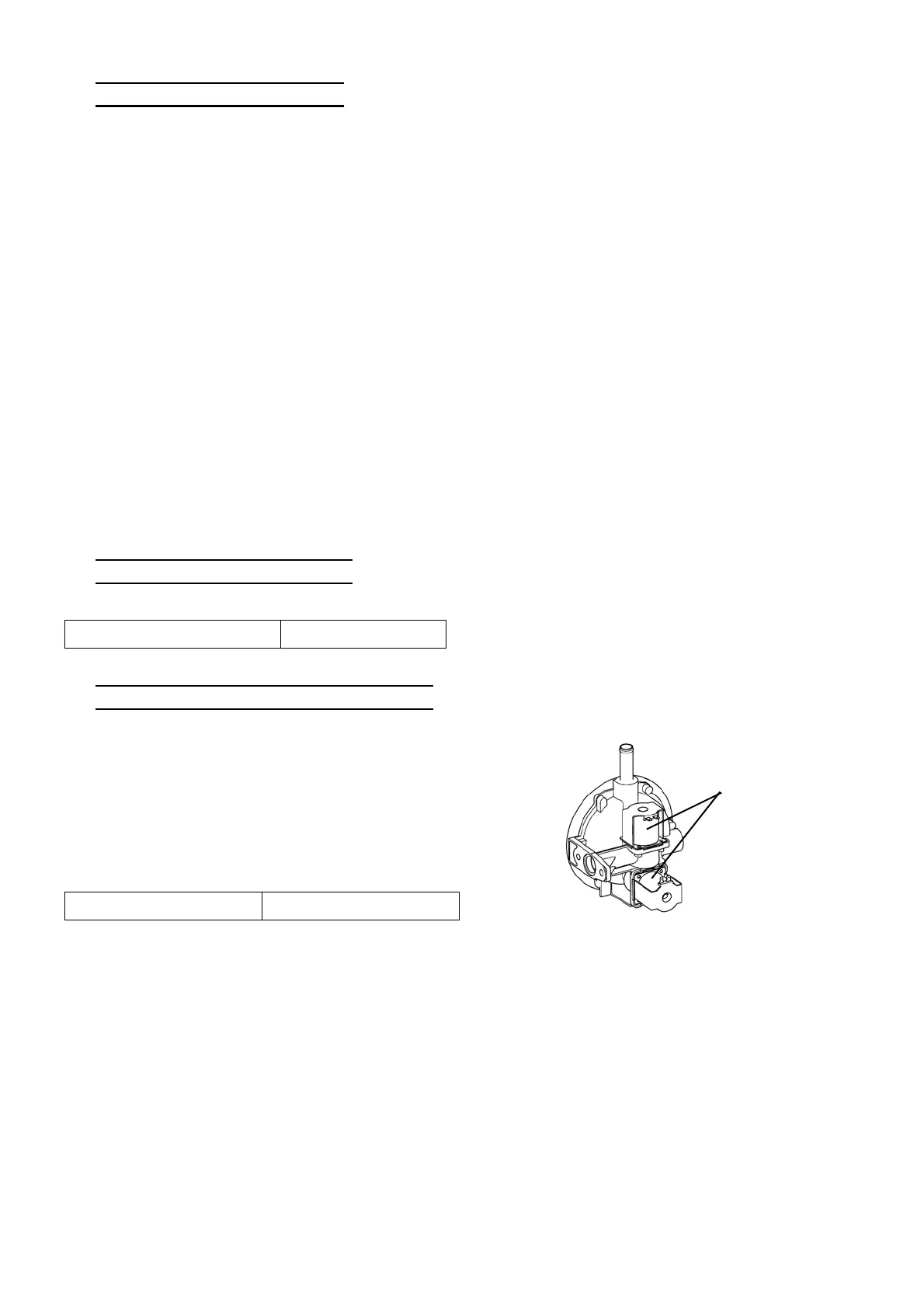
9) Inspect Electromagnetic Gas Valve
2. Check output voltage
1) Select "Actuators output status/individual actuating (code No. 20)" in the check mode of the board mainte-
nance functions. Then turn ON "Main side output permission", "Engine side output permission", and (alone
either "Electromagnetic gas valve 1" or "Electromagnetic gas valve 2") in order.
2) Check the output voltage (12 V DC) to the electromagnetic gas valve at each terminals (GV1: CN8[10]-[4],
GV2: CN8[11]-[5]) on the main PCB.
If the output voltage is not normal even though the "electromagnetic gas valve" is turned ON, the switching
circuits on the main PCB are considered to be faulty.
Standard pressure value 0.29 psi (2.0 kPa)
1. Inspect electromagnetic gas valve unit
1) Turn OFF the electric leakage breaker.
2) Disconnect the connector to the electromagnetic
gas valve, and measure the resistance between
the terminals on each of the two electromagnetic
gas valves for a magnet coil disconnection.
Standard resistance value 21.0 Ω
Electromagnetic
gas valves
 Loading...