198
TROUBLESHOOTING
4. Procedure for Inspection and Treatment
1) Check Power Supply System
1. Check that the power supply wires of the indoor and outdoor units are correctly connected as specified in the
installation manual.
2. Check that the power supply voltage (230 V AC or 208 V AC) is applied to indoor and outdoor units at the power
supply terminal.
2) Check Control Unit
1. Control unit on indoor units
Check the input/output voltage (230 V AC or 208 V AC) of the transformer in the indoor unit.
If 230 V ACor 208 V AC is not applied to the transformer, the fuse may be blown.
2. Control unit on outdoor units
1) Turn the power supply ON.
2) Check for power supply voltage (230 V AC or 208 V AC) in the outdoor unit.
If the LED 11 (yellow) on the main board does not light up even though 200 V AC is applied, the sub PCB or
the main PCB may be faulty.
Check the input/output voltage.
3) Locate Electric Leakage Positions
[Procedure for Locating Electric Leakage Positions]
1. Locate the 200 V system devices
Disconnect the connectors for the 200 V system devices (reversing valve, hot gas bypass valve, compressor
heater and oil bypass control valve) on the main PCB, the connectors (outdoor fan and engine coolant pump)
on the DCBL PCB, and measure insulation resistance. If the resistance recovers with these connectors discon-
nected, leakage occurs in any of the devices. Inspect each device for leakage.
2. Locate the remote control system
Disconnect the power supply wires to each indoor unit at the terminals on the terminal block and measure the
insulation resistance. If the resistance recovers, the indoor unit may be considered as a location of leakage.
NOTE) Never use a megohmmeter in the inspection of the communication system.
4) Check Remote Control System
Inspect the terminals of the indoor units and the remote controllers for a failure, such as contact failure, discon-
nection, etc.
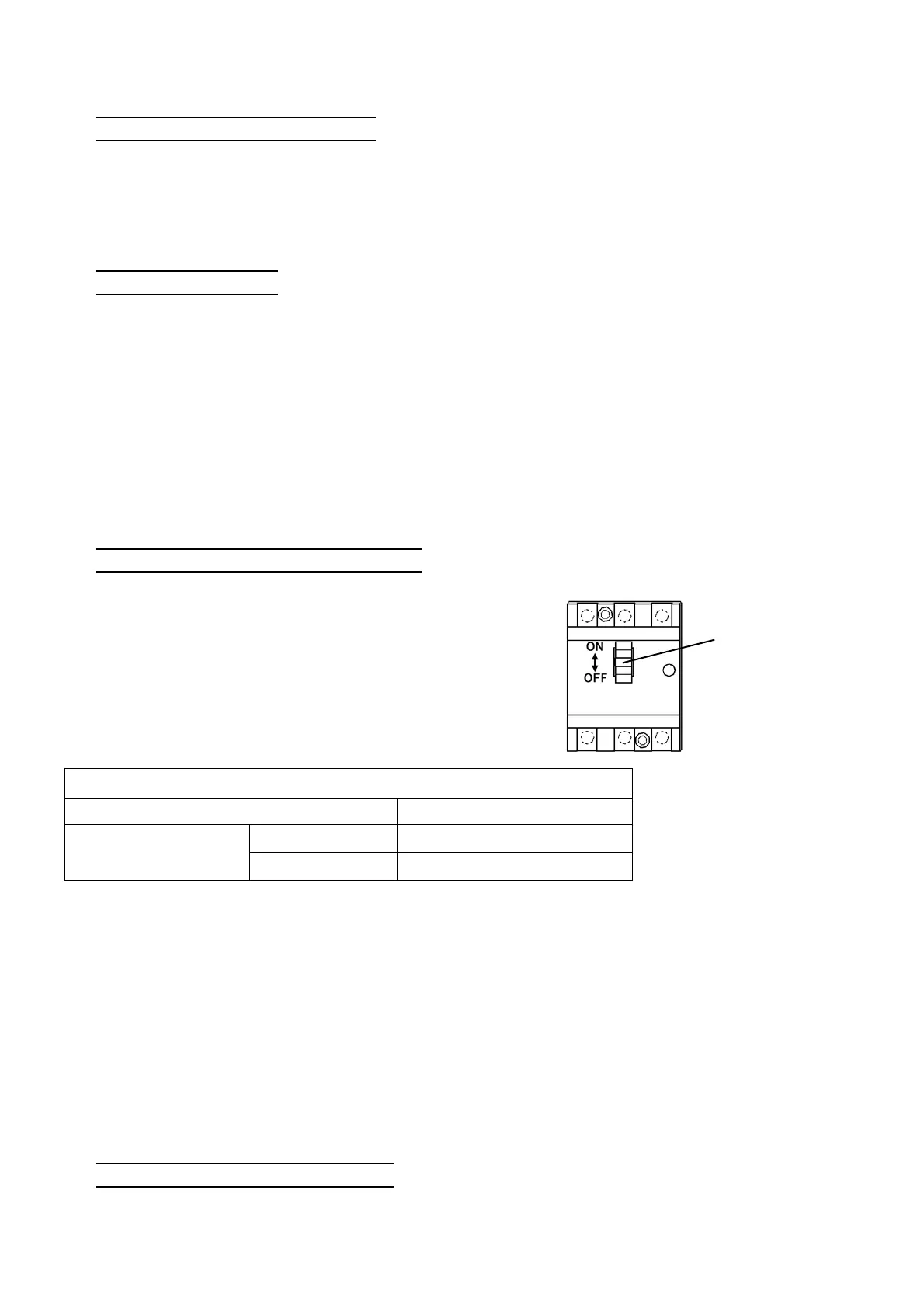
If the electrical leakage breaker activates, measure
the insulation resistance using a megohmmeter to
locate a leakage position.
Be sure to turn OFF the electrical leakage breaker
and disconnect the ground wiring (CN4) on the EMC
PCB before measuring the insulation resistance.
Eelectric leakage
breaker
Standard insulation resistance value
Measuring condition 500 V insulation tester
Variable resistor
Disconnected 10 MΩ or more
Connected 1 MΩ or more
 Loading...