199
TROUBLESHOOTING
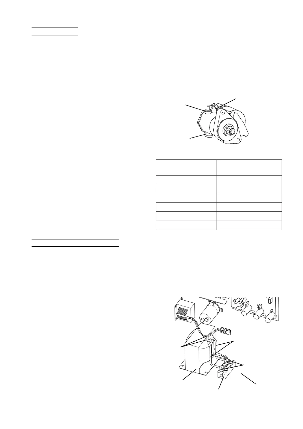
5) Inspect Starter
6) Inspect Starter Transformer
1. Check primary input voltage
1) Select "Actuators output condition/individual actuating (code No. 20)" in the check mode of the board
maintenance functions. Then turn ON "Main side output permission", "Engine side output permission",
and "Starter transformer" in order.
2) Check the input voltage (200 V AC) at CN11[6]-[12] on the main PCB.
1. Check output voltage applied to the starter
1) Output voltage applied to the starter motor.
(1) Select "Actuators output condition/individual actuating (code No. 20)" in the check mode of the board
maintenance functions. Then turn ON "Main side output permission", "Engine side output permission",
and "Starter transformer" in order.
(2) Check the output voltage (12 V DC) between the
B terminal of the starter and the body ground.
2) Output voltage applied to the pinion drive coil
(1) Select "Actuators output condition / individual
actuating (code No. 20)" in the check mode of the
board maintenance functions. Then check that
"starter ON" is displayed.
(2) Check the output voltage (12 V DC) between the
S terminal of the starter and the body ground.
2. Inspect starter unit
Turn OFF the power supply, and measure the
resistance at the locations shown in the right table.
Check that each measured value does not greatly
deviate from the standard value.
Location
Standard resistance value
(68 ℉ (20 ℃ ))
S terminal - Body ground 0.24 Ω
B terminal - Body ground ∞
M terminal - Body ground 0.01 Ω
S terminal - M terminal 0.24 Ω
S termina - B terminal ∞
B termina - M terminal ∞
B terminal
M terminal
S terminal
2. Check secondary output voltage
Check the output voltage (12 V AC) between the cath-
ode side and anode side of the diode (2 locations).
If output voltage at the secondary side (200 V AC) is
not normal although the input voltage on the primary
side (200 V AC) is normal, the starter transformer is
considered to be faulty.
3. Inspect starter transformer unit
Turn OFF the power supply, and check the insulation
resistance between the primary terminal and the sec-
ondary terminal.
Primary
terminal
Secondary terminal
Starter transformer
Diode
Cathode side
Anode side (ground)
 Loading...