134
CONTROL
CONTROL
1. System Control Functions
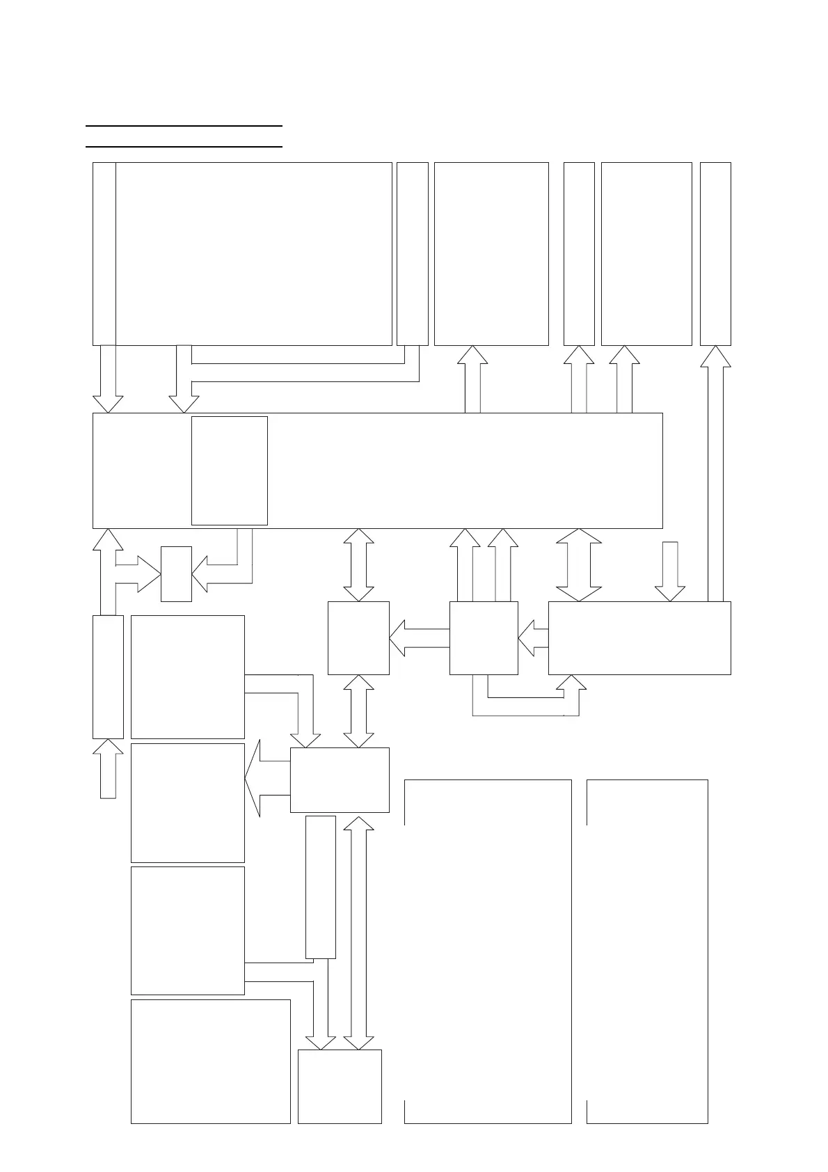
1) System Block Diagram
㩷 1. Under centralized
control
㩷 2. Operation mode
㩷
3. Set air volume
㩷
4. Wind direction
(Fixed/ Swing)
㩷 5. Set temperature
㩷 6. Timer time
㩷
7. Filter sign
㩷 8. Defrosting / Hot start
㩷 9. Error code
10. Operation lamp
11. Inspection / Test
operation display
12. Under master control
㩷 1. Run / Stop
㩷 2. Operation switching
㩷 3. Air volume control
㩷
4. Wind direction control
㩷
5. Temperature control
㩷 6. Timer setting
㩷 7. Timer time
㩷 8. Filter reset
㩷
9. Inspection / Test
operation button
㩷 1. Fan motor
㩷 2. Swing flap
㩷 3. Drain motor
㩷 4. Connector for
external control
adapter
㩷 5. Electronic expansion
valve
㩷 1. Indoor intake air
temperature sensor
㩷 2. Indoor vapor pipe
temperature sensor
㩷 3. Indoor liquid pipe
temperature sensor
㩷 4. Float switch
㩷 5. Limit switch
㩷㩷䋨Swing flap䋩
㩷 6. External input
Indoor unit㩷㸢㩷Remote controller
㩷 1. Run / Stop
㩷 2. Operation mode
㩷㩷㩷(Dehumidifying / Cooling /
Fan / Heating)
㩷 3. Fan air volume
㩷 4. Wind direction
㩷 5. Set temperature
㩷 6. Filter sign
㩷 7. Defrosting / Hot start
㩷 8. Under centralized control
㩷
9. Indoor unit address number
10. Error code
11. Under master control
Remote controller㩷㸢㩷Indoor unit
㩷 1. Run / Stop
㩷 2. Operation mode
㩷㩷㩷(Dehumidifying / Cooling /
Fan / Heating)
㩷 3. Fan air volume
㩷 4. Wind direction
㩷 5. Set temperature
㩷 6. Filter reset
䋨7. Remote controller sensor
temperature䋩
㩷 * When using a remote controller
with the sensor
Remote
controller
㩷 1. Remote controller sensor
㩷 2. Main / Sub selector switch
Input signal
Indoor unit
㩷 1. Refrigerant high pressure switch
㩷 2. Engine oil pressure switch
㩷 3. Engine coolant temperature sensor
㩷 4. Outside air temperature sensor
㩷 5. Compressor discharge pipe
temperature sensor
㩷 6. Compressor intake temperature
sensor
㩷 7. Engine compartment temperature
sensor
㩷 8. Sub heat exchanger liquid
temperature sensor
㩷 9. Outdoor liquid pipe temperature
sensor
10. Heat exchanger liquid temperature
sensor
11. Heat exchanger vapor temperature
sensor
12. Accumulator outlet temperature
sensor
13. Refrigerant high pressure sensor
14. Refrigerant low pressure sensor
15. Engine speed sensor
16. Voltage sensor (starter, igniter)
17. Engine exhaust air temperature
sensor (option only)
18. Oil level switch
With board maintenance function
㩷 1. EEP dip switch
㩷
㩷 1. Throttle valve
㩷 2. Fuel gas flow control valve
㩷 3. Igniter
㩷 4. Outdoor heat exchanger liquid flow
control valve
㩷 5. Sub heat exchanger liquid flow
control valve
㩷 6. Su䌢cooling valve
㩷
㩷
7. Oil bypass control valve
㩷
8. Electromagnetic gas valve
㩷 1. Ignition coil
㩷 2. Compressor clutch
㩷 1. Reversing valve
㩷 2. Hot gas bypass valve
㩷 3. Compressor heater
㩷 4. Electromagnetic compressor capacity
valve
㩷 5. Exhaust water drain heater
(option only)
㩷 6. Engine oil pan heater (option only)
Maintenance devices
Input signal
Setting on
Output (DC 12V)
Power supply
board
Power supply
for control
Ignition system
power supply
Control
signal
DC 280V
DC 12V
DC 12V
㩷 1. Fan motor
㩷 2. Engine coolant pump
PWM out
ut
AC 200V
DCBL board
Display
C200V
Communication
I/F board
Power supply
for control
DC 16V
Communication
Communication
Communication
Power supply
for control
DC 15V
Out
ut
Input signal
AC / DC converter
䋨Transformer, diode䋩
C 200V
DC 12V
Starter
Communication
Drive signal
Output (DC 12V)
Output (AC 200V)
Operation
Communication items between remote controller and indoor unit
Outdoor unit controller
Main board
䊶Running hours display
䋨Board maintenance
function䋩
䊶Error monitor (Red)
Indoor unit㩷㸢㩷Outdoor unit
㩷 1. Run / Stop
㩷 2. Operation mode
㩷㩷㩷(Dehumidifying / Cooling /
Fan / Heating)
㩷 3. Temperature control request
㩷 4. Error code
㩷 5. Intake air / Heat exchanger
temperature
Outdoor unit㩷㸢㩷Indoor unit
㩷 1. Compressor status
㩷 2. Operation mode
㩷 3. Defrosting signal
㩷 4. Error code
Communication items between indoor unit and outdoor unit
 Loading...