234
TROUBLESHOOTING
Function and display of each mode
Display contents of error sign (error LED)
One flashing cycle is composed of 10 flashes (on/off). (EX. 7 flashes ··· 7 "on"s and 3 "off"s out of 10 "on"s.)
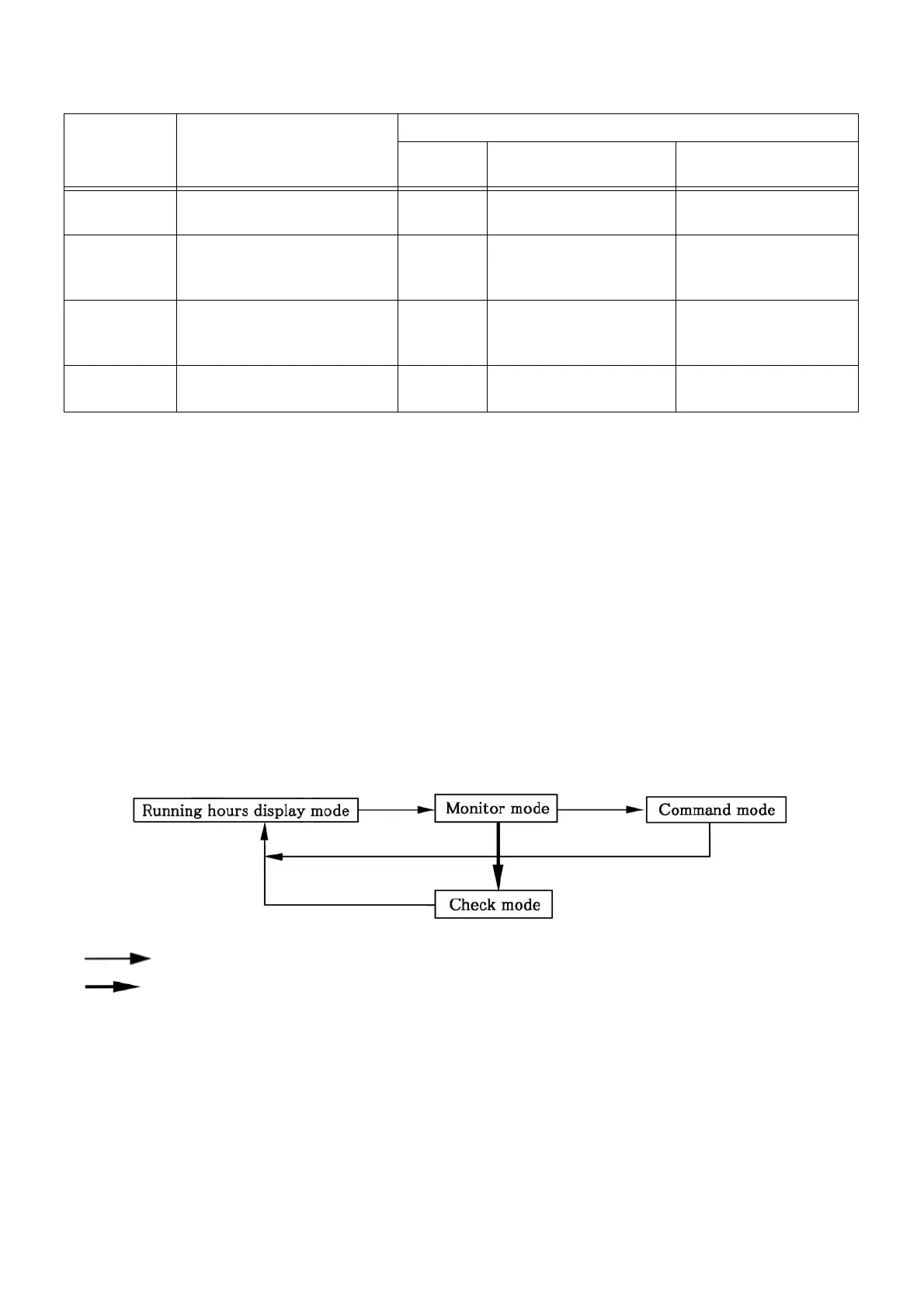
Method of switching modes
NOTE)
In the following cases, check mode is not available.
(1) Less than approximately 20 seconds after power ON
(2) When the maintenance checker is connected
(3) During remote control operation
(4) During engine operation
When the maintenance checker is connected during check mode, check mode continues although the board
maintenance function display is changed to running hours display mode.(Check mode can be cancelled with a
maintenance checker.)
When none of the switches are operated for 10 minutes, the display returns to the running hours display mode.
Mode Main functions
Mode indicator LED
Normal
During maintenance set-
ting
Check mode
(setting from a PC)
Running hours
display
Running hours and other
information display
OFF
Repeat of 5 red-green
flashes/off
Repeat of 3-second red
lighting up/off
Monitor
Various input / output data
display
Green
lights up
Repeat of 5 red flashes/
green lighting up
Repeat of 3-second red
lighting up/7-second
green lighting up
Command
Commands for operation start
/ engine speed, etc.
Red/Green
light up
Repeat of 5 red-green
flashes/red-green
lighting up
-
Check
Rewriting the stored data, or
activating individual devices
Red lights
up
Repeat of red lighting up/
5 green flashes
-
Error : Always flashing ↑Higher display priority
Alert : Flashs 9 times
Warning : Flashs 8 times
Error standby : Flashs 7 times
In abnormal compressor discharge pipe temperature avoidance : Flashs 5 times
In high pressure avoidance : Flashs 4 times
In abnormal engine coolant temperature avoidance : Flashs 3 times
In low pressure avoidance : Flashs 2 times
Normal : OFF ↓Lower display priority
: Press [MODE] switch for 1 second
: Press [SET] + [CLEAR] switches simultaneously for 2 seconds
 Loading...