307
TROUBLESHOOTING
#TTCPIGOGPVKPVJGEQPVTQNDQZ
%0
Ԙԙ
$M 4
%0
9$
)
9$M
ԡԛ
)T4
ԢԜ
)8 )8
+)
+)
+)
%0
ԚԘԙԞ Ԡ
$M9;$N4
%2
ԣ
9
%0
%2
8
$8
%2
*
%2
*
28
;;
ԜԢ
44
ԙԟ
99
ԛԡ
44
ԘԞ
Ԙ
ԙ
64
%
&$
Ԙ
ԙԜԚ
564
%0
ԝԣ
99
%0
ԝԚԘ
;14
ԙԛ
1;
1.2
%0
6*1
')
4
')
'
96
99
Ԥԥ
$M$M
Ԣԣ
;;
Ԟԟ
44
Ԡԡ
$T$T
Ԛԛ
ޚ
ޚ
$T4$N1;9
ԫ
(7'.
$T4$N1;9
ԧԩԪ ԦԨ
56/
ޚ
ޚ
ޚ
ޚ
$N$N
Ԡ
%2
8
4;
5CHGV[
ITQWPFKPI
)T;
5CHGV[
ITQWPFKPI
RVKQPCN
PPGEVQT
QVWUGF
%0
'/%
2%$
)
%0
Ԙԙ
49
Ԙ
$
Ԙԙ
49
%0 %0
ԛԜ
%0
㧱㧸㧮
#%8
QT
#%8
.
6$
0
49
%0
ԘԙԚԛԜ
$M$N;94
ԙԘ
9$T
%0
'0-
2%$
ԘԙԚԛԜ
%0
4Ԙ
9ԝ
$Ԛ
+)0
)555$
%%%$
Ԝ
4
%0
64
䌉䌆㪄䌐䌃䌂
㪤㪘㪠㪥㪄䌐䌃䌂
䌅䌌䌂
㪜㪤㪚䋭䌐䌃䌂
䌐䌗䌒䋭䌐䌃䌂 䌄䌃䌂䌌㪄䌐䌃䌂
㪧㪘㪥㪜㪣䋭㪘㪪㪪㪰
㪜㪥㪢㪄
㪧㪚㪙
㪢㪩㪄
㪧㪚㪙
Ԛ
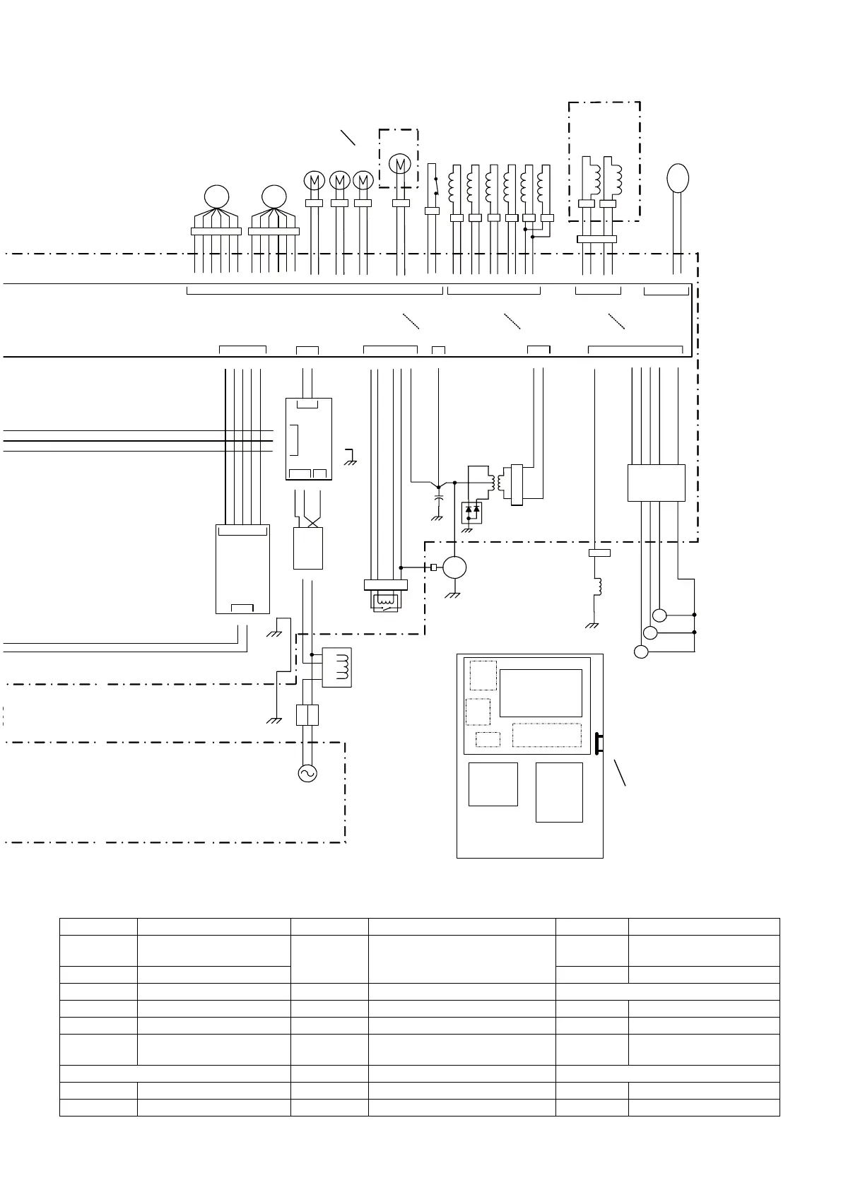
Heat exchanger
compartment
Unit with deodorant kit only
Unit with drain heater
kit only
NOTE) The status of contact point shown in the diagram is when the system is shut down.
IG1 Ignition coil 1 EMC-PCB EMC PCB IGN Igniter
IG2 Ignition coil 2
KR-PCB
Cold district PCB
(unit with drain heater kit only)
IF-PCB
Communication control
PCB
IG3 Ignition coil 3 ELB Eelectric leakage breaker
WB(G2) Engine speed sensor DCBL-PCB DCBL PCB Heat exchanger compartment
STM Throttle valve C Electrolysis condenser FM1 Fan motor 1
STR Starter ENK-PCB (Not use) FM2 Fan motor 2
TR2 Transformer 2 DB Diode bridge THO
Outside air temperature
sensor
Control box RY1 Starter relay Fuel box
MAIN-PCB Main PCB TR1 Transformer 1 GV1 Electromagnetic gas valve 1
PWR-PCB Power supply PCB L Reactor GV2 Electromagnetic gas valve 2
 Loading...