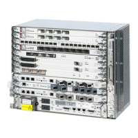
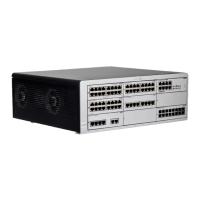
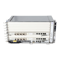
6 — 9500 MPR/9500 MPRe shelf object configuration
6-4 September 2013 Alcatel-Lucent 5620 Service Aware Manager, Release 11.0 R5
3HE 08459 AAAA TQZZA Edition 01
MPR User Guide
Core-enhanced card
The core-enhanced card in slot 1 provides the following:
• device management and control functions
• DC power
• a plug-in flash memory card to store device configuration and license data
• an Ethernet switch that implements the cross-connections between the radio
modem or 32 × DS1 / 32 × E1 cards, between the Ethernet user ports, and between
the Ethernet ports and the radio modem or 32 × DS1 / 32 × E1 cards
• four electrical Ethernet ports; port 4 can be used as another management port, if
required
• two SFP Ethernet ports; the ports are supported by the 5620 SAM when an SFP
MDA is installed
• up to six MPT radio ports; ports 1 to 4 support MPT-HC, MPT-HCv2, and
MPT-MC; ports 5 and 6 support MPT-HC, MPT-HCv2, MPT-HL, and SFP
An optional identical core-enhanced card can be installed in card slot 2. The card
provides protection if the card in slot 1 fails.
The MPT-HL does not support radio LAGs or 1+1 protection configurations. See the
9500 MPR user documentation for information about supported cross-connections
for the MPT-HL and core-enhanced card.
When an MPT pair (MPT-HC or MPT-HCv2 with RPS module, or MPT-MC) is
used for a protected configuration, both MPTs must use the same type of GigE port
(optical or electrical) to use the same IDU-ODU synchronization method.
A protected configuration is only allowed between ports 1 - 2, 3 - 4, and 5 - 6.
The following protection types are supported when MPT-HC or MPT-MC is used as
an ODU in a split-mount configuration and directly connected to a core-enhanced
card:
• radio protection switching (RPS)
RPS is always supported in 1+1 radio configurations (FD and HSB). RPS is
implemented directly on a pair of MPTs.
• transmission protection switching (TPS)
TPS is always supported in 1+1 HSB radio configurations.
• equipment protection switching (EPS)
EPS protects the MPT and cables connecting the MPT to the IDU. RPS protection
always assumes the MPT EPS.
When an MPT ODU protection group is configured on a core-enhanced card:
• the MPT ODU connected to port 1 (electrical), port 3 (electrical), or port 5
(optical) is defined as main
• the MPT ODU connected to port 2 (electrical), port 4 (electrical), and port 6
(optical) is defined as spare
See Procedure 7-12 for information about adding 9500 MPR port protection.