Hardware Description
Page 26 7210 SAS-T Installation Guide
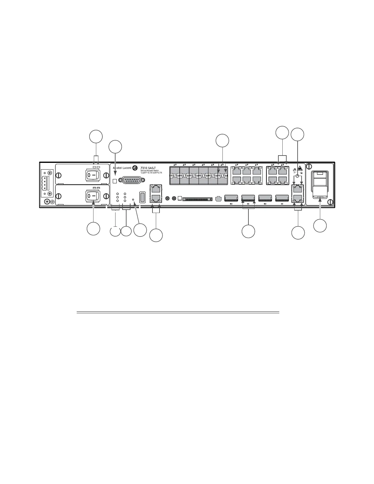
System LEDs and Buttons
The various system LEDs and buttons are located on the front panel of the chassis. See Figure 11
for the location/ of the system LEDs and buttons, Table 7 for key descriptions, and Table 8 for
alarm descriptions.
Figure 11: System LEDs and Buttons
Crit
Maj
Fan
Status
PS1
PS2
USB
Alarm
–48V +12V
DC ETR
PEM
200W
– 48V +12V
DC ETR
PEM
200W
CF2
OMC
23 24 25 26
Management
Fan
1PPS
BITS2/ToD2
BITS1/ToD1
10MHz
ACO
1 2 3 4 5 6 7 8 9 10 11 12 13 14 15 16 17 18 19 20 21 22
–A
+A
–B
+B
SAS_T_009
Reset
2
4
3
5
6
1
7
8
9
12
13
10
11
Table 7: 7210 SAS-T System LEDs and Buttons
Key Description
1 Power tray LED
2 Power tray switch
3 Alarm cut off button
4Alarm LED
5 Power status LED
6 Reset button
7 BITS port LED
8 10G XFP port LED