Installing the 7210 SAS-T
7210 SAS-T Installation Guide Page 41
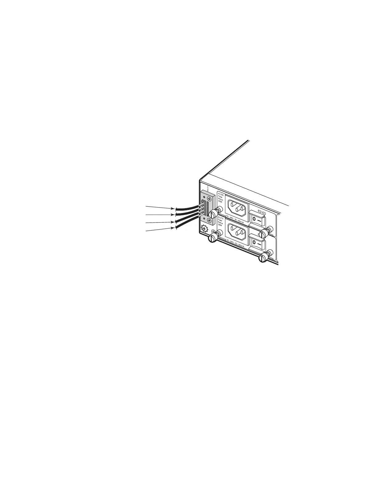
Step 3 The wiring between the DC power supply and the switch must be stranded copper wire
within the range of 16 to 20 AWG in accordance with local electrical codes.
Step 4 Connect the VDC power feed using the VDC input and RETA/B (return) lines for power
source A and B, respectively. Insert the wires into the DC input plug (using a small flat-
tip screwdriver). Color code the wiring according to local standards to ensure that the
input power and ground lines can be easily distinguished.
Figure 16 illustrates how to connect a -48 VDC power source to the chassis:
Figure 16: Connecting to a -48 VDC Power Source
-48V (A) (Pin 1)
Return (A) (Pin 2)
-48V (B) (Pin 3)
Return (B) (Pin 4)
SAS_T_029