Publication 1394-5.0 — May 2000
Specifications A-31
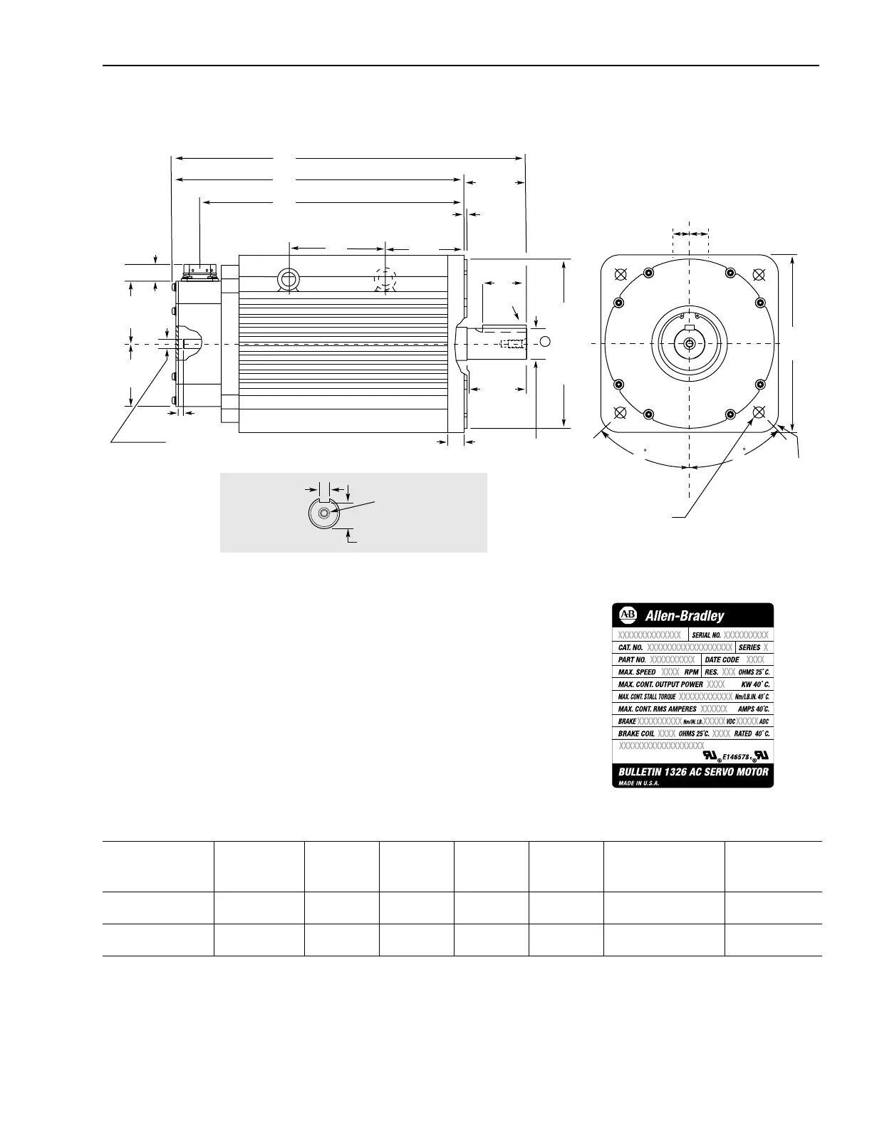
Figure A.23
1326AS-B8 Series Servo Motor
!
Shaft and Pilot Tolerances
Shaft Runout 0.05 (0.002) T.I.R
Shaft Endplay 0.025 (0.001)
Pilot Eccentricity 0.10 (0.004) T.I.R
Maximum Face Runout 0.10 (0.004) T.I.R
Flange Mount in millimeters and (inches)
Catalog number Description
1
AL AD AG C Key End milled
keyway
(full depth)
1326AS-B840
x
-21 without brake 131
(5.15)
308
(12.13)
346
(13.63)
431
(16.97)
12 x 8 x 60
(0.472 x 0.315 x 2.36)
60
(2.36)
1326AS-B860
x
-21 without brake 235
(9.25)
359
(14.13)
397
(15.63)
482
(18.97)
12 x 8 x 60
(0.472 x 0.315 x 2.36)
60
(2.36)
1
If you are ordering a 1326AS-B8
xxxx
-21-K8 with an optional 24V DC 50.9 N-m (450lb-in.) brake, add 103 mm (4.05 in.) to AD, AG and C. Add 51 mm (2.0 in) to AL.
Dimensions are per NEMA Standards MG 7-2.4.1.3 and IEC 72-1. Shaft and pilot tolerances are per DIN 42955, N tolerance. The eye bolt diameter is 38.1 mm (1.50 in)
O.D. x 22.35 mm (0.88 in) I.D.
Shaft Detail
241 sq.
(9.49)
45
45
C
AG
AD
60
(2.36)
230.000/229.954
9.055/9.053
81.0 ± 0.3
(3.19)
4.0 ±0.2
(0.157)
22.4
(0.882)
7.7/6.2
0.305/0.245
85.0±0.5
(3.35)
42.000/41.984
(1.654/1.653)
0.4997/0.4990
12.692/12.675
23
(0.91)
12.00/11.96
(0.472/0.471)
M8 x 1.25 Tapped hole
20 (0.79) Deep min.
37.00/36.80
(1.457/1.449)
15 mm Dia. Thru-hole
4 required on a 265 mm Dia. B.C.
85
(3.35)
85
(3.35)
25
(0.98)
33
(1.3)
1
Key
73.15
(2.88)
AL
Motor Front End
Cap Corner Radius
25.4
(1.00)
+_
.397 (.015)
Name Plate Detail

 Loading...