Publication 1394-5.0 — May 2000
2-10 Installing Your 1394 (applies to all systems)
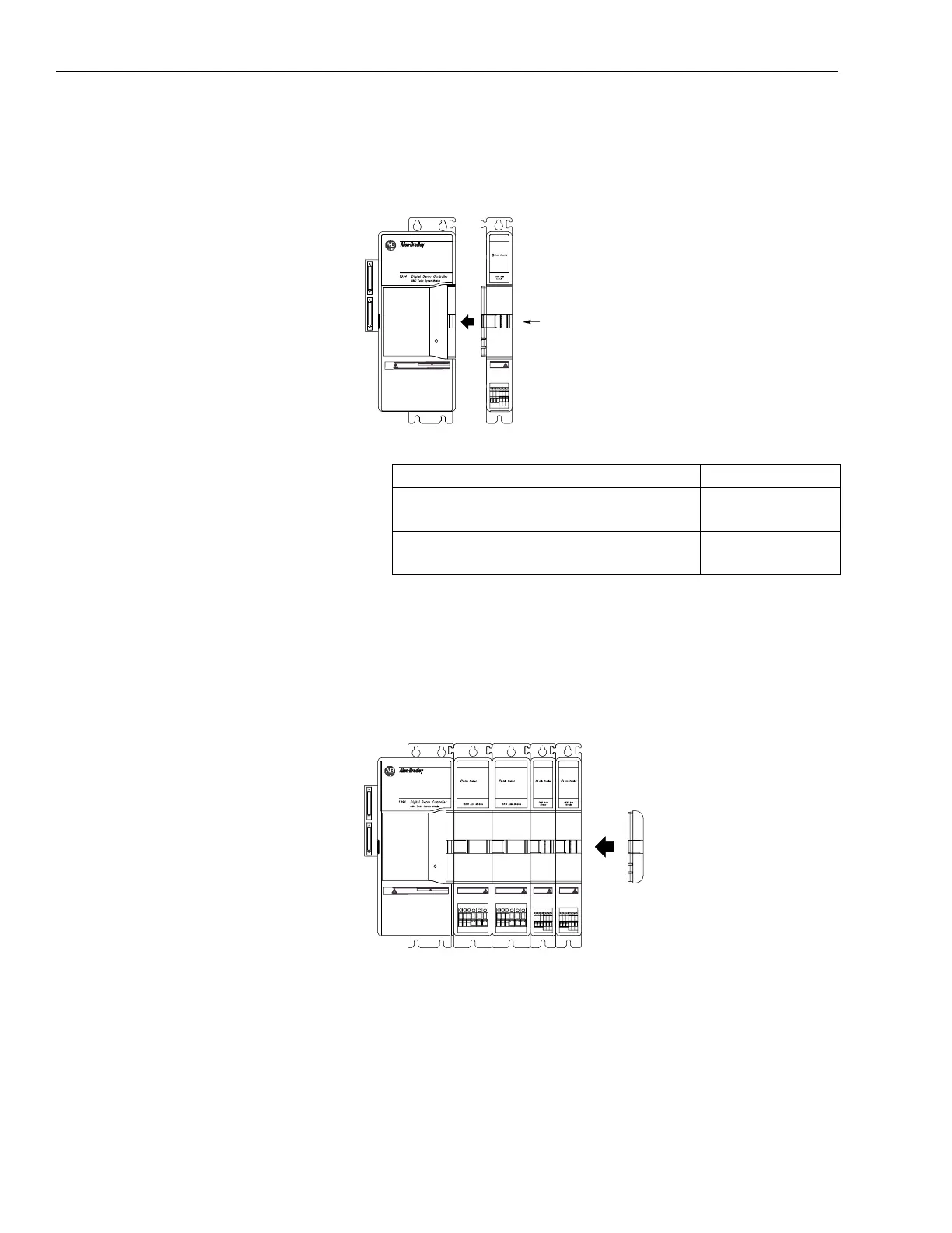
6. Slide the slide-and-lock mechanism on the axis module to the left
until it locks into place.
Figure 2.8
Slide-and Lock Mechanism
7.
8. Install the lower fasteners for the system module and all axis
modules.
9. Attach the terminator to the last axis module. Slide it to the left
until it locks in place.
Figure 2.9
Attaching the Terminator
Important: The terminator terminates the serial ring and provides
protection for the DC Link. The 1394 system will not
operate without the terminator.
10. Tighten all mounting fasteners.
Slide-and-Lock
Mechanism
Status
DANGER
RISK OF ELECTRICAL SHOCK. HIGH VOLTAGE MAY
EXIST UP TO FIVE MINUTES AFTER REMOVING POWER.
If you: Do this:
Have more axis modules for this system
module
Go to main step 3.
Do not have more axis modules for this
system module
Go to main step 8.
Status
Attach the
Terminator
DANGER
RISK OF ELECTRICAL SHOCK. HIGH VOLTAGE MAY
EXIST UP TO FIVE MINUTES AFTER REMOVING POWER.

 Loading...