Publication 1394-5.0 — May 2000
3-34 Wiring System, Axis, and Shunt Modules, and Motors (for all systems)
5. Insert the other wire from the 230V AC power supply into
terminal 4.
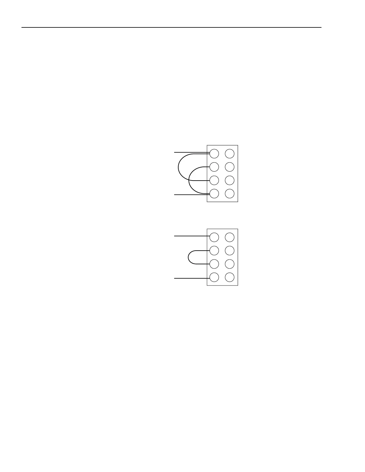
6. Insert the jumper wire that came with your shunt module into
terminals 2 and 3. Refer to Figure 3.21 for the jumper’s location.
7. Tighten all screw terminals.
8. Gently pull on each wire to make sure it does not come out of its
terminal. Re-insert and tighten any loose wires.
Figure 3.21
Wire Locations for the Shunt Module Fan
1
2
3
4
Wiring the fan for 115V
1
2
3
4
Wiring the fan for 230V
To power supply
To power supply
To power supply
To power supply

 Loading...