Geometries with orientation support
Rockwell Automation Publication MOTION-UM002F-EN-P - February 2018 141
Work Frames Work ID
Work Frame Offsets
Work Frame 3 2 50 -100 -800 0 0 180
Work Frame 4 3 -100 -50 -800 0 0 90
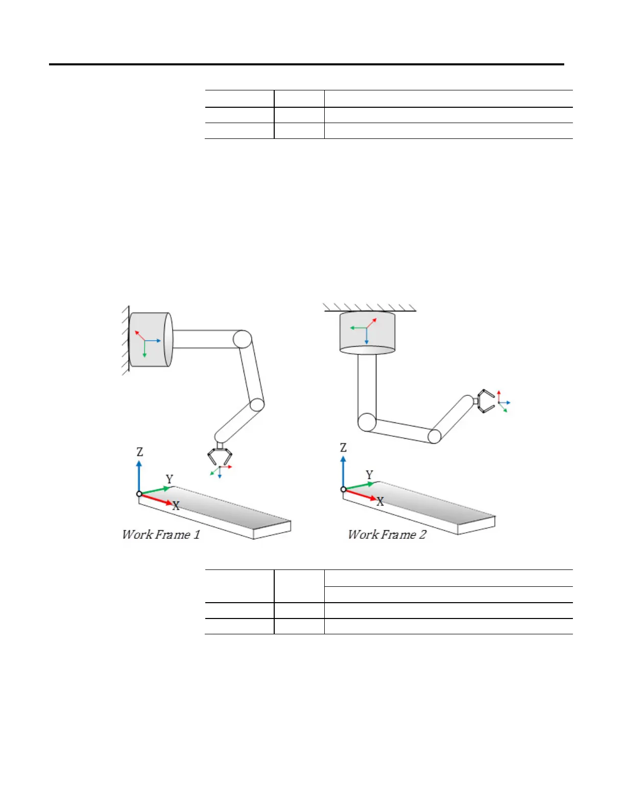
Work frames with different robot positions
It is acceptable to mount robots with different orientations, such as upside down
and horizontal positions. Work frame offsets set the relationship between the
work frame and the base frames so that programing the target position is
convenient for the users.
This diagram illustrates robots mounted in horizontal and upside down positions.
Work frame offsets 1 and 2 convert the target positions to conveyor coordinate
system assuming it is placed on the ground.
Work Frames Work ID
Work Frame Offsets
X Y Z Rx Ry Rz
Work Frame 1 0 100 500 100 90 0 90
Work Frame 2 1 -100 100 500 180 0 90
 Loading...

