x530L Series Installation Guide for Virtual Chassis Stacking
105
The following procedure assumes that you have already reviewed
the information and performed the procedures in Chapter 3,
“Beginning the Installation” on page 89.
To install the switch on a table, perform the following procedure:
1. Place the switch upside down on a table.
2. Insert a rivet housing into a bumper foot. Refer to Figure 43.
Figure 43. Inserting the Rivet Housing into the Bumper Foot
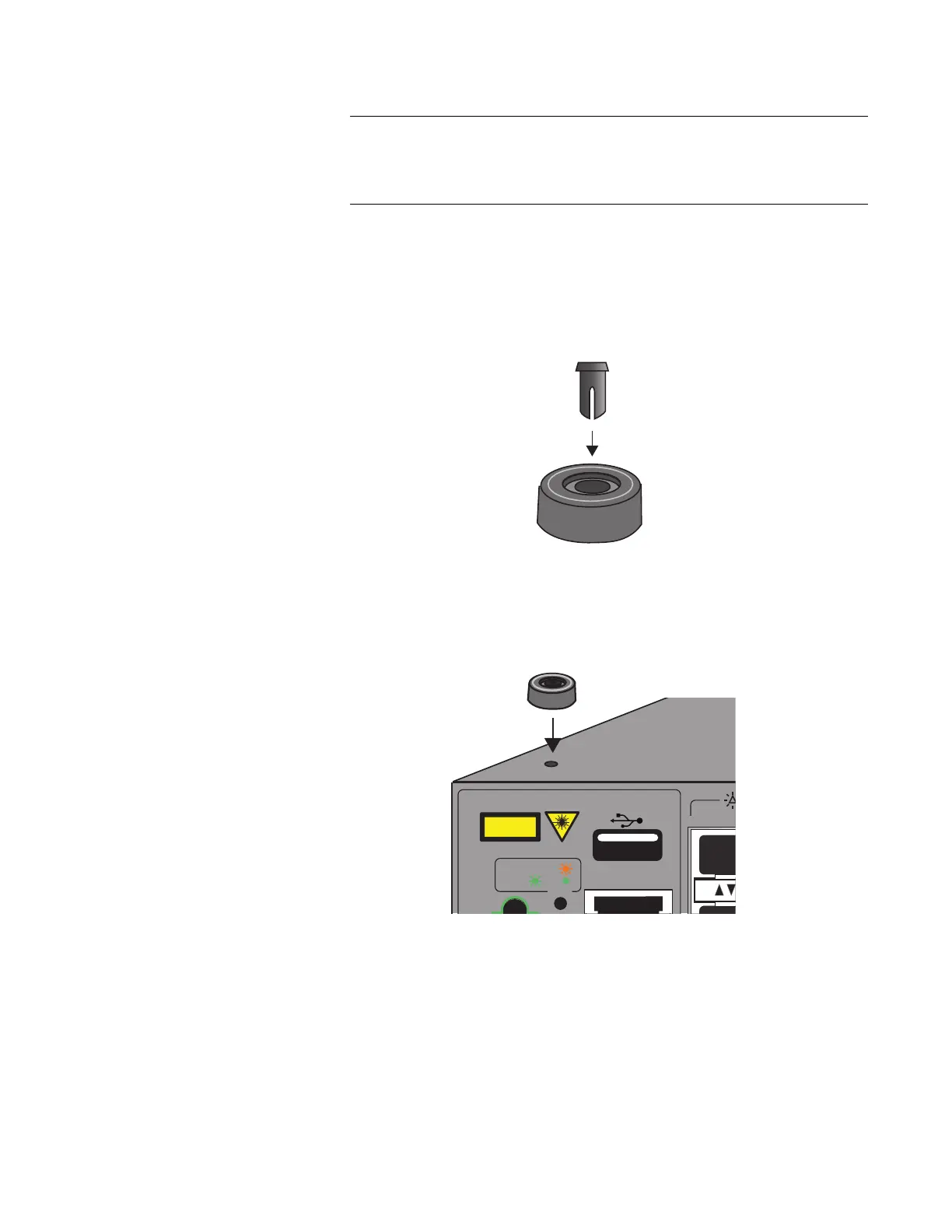
3. Place the bumper foot with rivet housing onto one of the holes in the
base of the switch. Refer to Figure 44.
Figure 44. Placing the Bumper Foot on a Base Corner Hole
4. Insert the rivet to secure the bumper foot to the base. Refer to Figure
45 on page 106.
USB
ON ACT
ERR
CLASS 1
LASER PRODUCT
CONSOLE

 Loading...


