Chapter 4: Installing the Switch on a Table
106
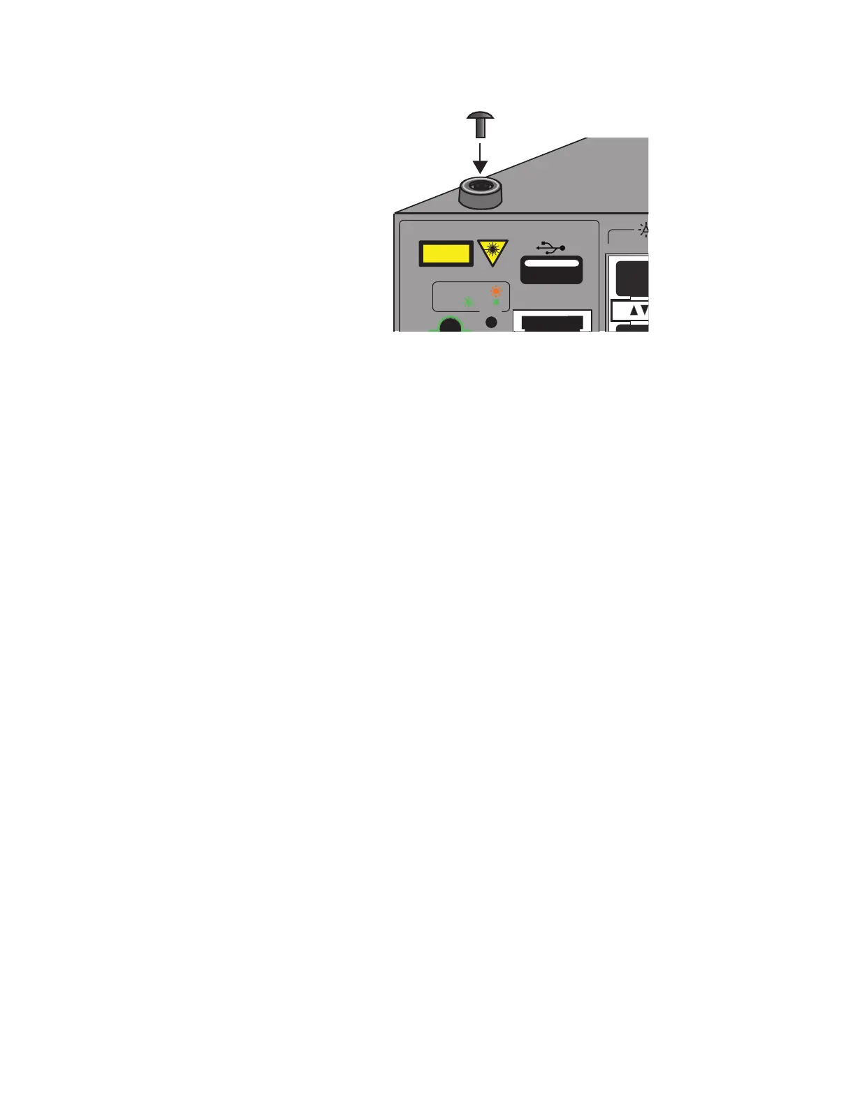
Figure 45. Inserting the Rivet into the Bumper Foot
5. Repeat steps 2 to 4 to install the remaining bumper feet.
6. Turn the switch over and place it on a flat, secure desk or table,
leaving ample space around it for ventilation.
7. After installing all the switches of the stack, do one of the following:
To build the stack with the default stacking ports, go to Chapter 7,
“Building the Trunk with the Default 10Gbps Stacking Ports” on
page 141.
To build a stack of x530L-10GHXm and x530L-18GHXm switches
using 5Gbps ports for the trunk, refer to Chapter 8, “Building the
Stack Trunk with 5Gbps Multi-Speed Ports” on page 161.
USB
ON ACT
ERR
CLASS 1
LASER PRODUCT
CONSOLE

 Loading...


