x530L Series Installation Guide for Virtual Chassis Stacking
113
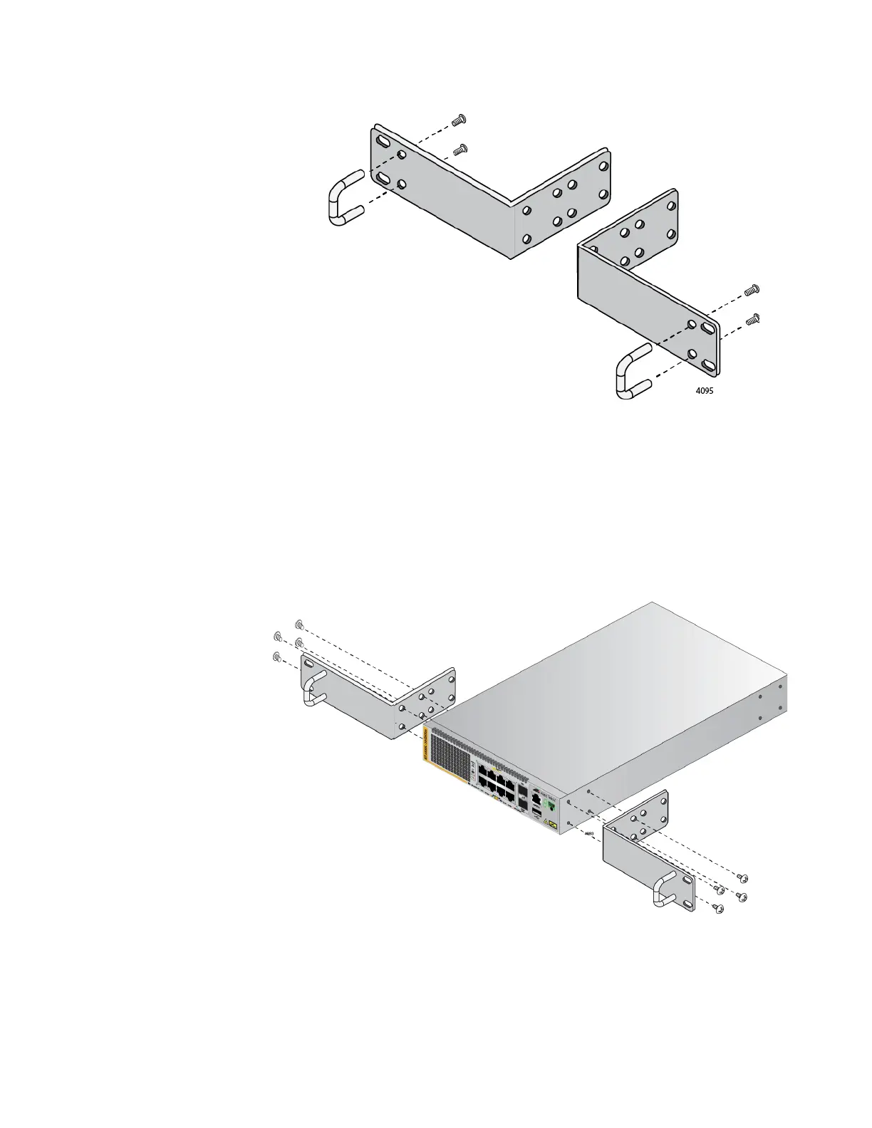
Figure 53. Attaching the Handles to the RKMT-J14 Brackets
2. Place the switch on a level, secure surface.
3. Attach the two brackets to the sides of the switch in the selected
position, using the eight M4x6mm screws included with the unit. (Refer
to Figure 51 on page 111 and Figure 52 on page 112.) The illustration
in Figure 54 shows the installation of the brackets such that the front
panel of the switch is even with the front of the equipment rack.
Figure 54. Attaching the RKMT-J14 Brackets to the Switch

 Loading...