Operating manual ALPHASEAPILOT MFC Issue 1.1 Page 28 of 84
ALPHASEAPILOT MFC
2.4 The CONTROLS Menu
The Controls Menu is rapidly and conveniently entered from all Autopilot operating modes
(STANDBY, ON, TRACK etc.) by single press operation of the “CONTROLS” key.
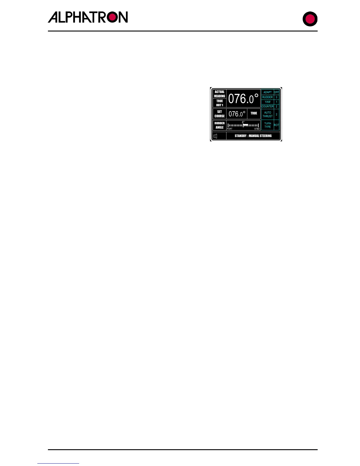
Adjustable control parameters are listed on the right
side of the operational display (as shown) and each
item is selected by further use of the “CONTROLS” key
accompanied by “flashing” to confirm parameter
selected. The value – or state – of the chosen item is
then changed via the rotary (+/-) illumination control.
2.4 (i) Adaptive / Non Adaptive Selection
The Adaptive and Non Adaptive operating modes are briefly discussed in
Section 2.3 and, in most cases, Adaptive selection will be preferred.
NB. Adaptive (automatic) “Weather” control adjustment is a Type Approval requirement of
High Speed Craft (HSC) Autopilots thus the Adaptive Mode must be selected for HSC
applications.
a) Use the “CONTROLS” key to enter the Controls Menu.
b) Use the “CONTROLS” key again to select “ADAPT” box followed by flashing
“ON/OFF”.
c) Use the rotary (+/-) illumination control to select “ON” or “OFF” as required
(Adaptive mode “ON” or “OFF” where OFF = PID).
2.4 (ii) Rudder Control
In the Adaptive Mode, the “value” of the RUDDER parameter will be found automatically
(after initial Sea Trial calibration) by reference to input speed and draft data etc. Even so,
the RUDDER value can be manually changed – if required to immediately optimise the
steering performance – via the CONTROLS Menu.
If Non Adaptive operation is in use, it will always be necessary to adjust the RUDDER value
manually – again via the CONTROLS Menu.
The Rudder Control defines the angle of Rudder that shall be applied in relation, or
proportion to course error (degrees off course).
The Control value is 1 to 9 (as shown against RUDDER in the CONTROLS Menu) and
minimum Rudder is applied at a setting of 1. Maximum Rudder is therefore applied at a
setting of 9 and a 3:1 ratio exists between minimum and maximum settings.
The factory default setting (accessible via the Set Up Menu) initially provides a Rudder
Control range of 0.5
o
to 1.5
o
of Rudder per degree course error.