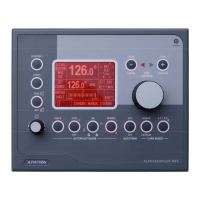
All ALPHASEAPILOT MFC Autopilot system Control Units are identical and may be used in
Master/Slave configurations as required up to a maximum of 3 Control Units per system.
NB. Where one than one Control Unit is involved it is important to note that each must have its
own dedicated address (No.1, No.2 or No.3).
(At power up, all Control Units display a splash screen – Section 2.14 – showing current address
status details etc. If two addresses are the same, this will produce a communication conflict
thus address changes will be required. (See Section 3.0 of the Installation and Technical
Manual).
When two or three Control Units are correctly installed with different address numbers, address
No. 1 will normally assume Master status. If it is required to change Master status to No.2 or
No.3, this can be achieved by simultaneous operation of the subject ON and REMOTE keys as
follows:-
a) Check that the current Master unit (normally address No.1) is switched ON with its
REMOTE key also ON to enable other stations entry to the Autopilot system.
NB. If there is doubt which Control Unit is the current “Master”, note that initial power
up will display either Master or 2
nd
station on the splash screen. (See Section 2.14).
b) Set the new required Master station to STANDBY.
c) Use the ON and REMOTE keys simultaneously for a period of 5 seconds to transfer
Master status to the subject Control Unit confirmed by a double bleep.
d) Check transfer by powering down and powering up again when the splash screen should
confirm “Master Station” on the subject Control Unit. (Similarly, the previous Master
station should now show “2
nd
Station” on its splash screen when powered down and up
again).