EasyManua.ls Logo

AMF-BRUNS K90 ACTIVE - Electrical Circuit Diagrams

Default Icon
100 pages
Print Icon
To Next Page IconTo Next Page
To Previous Page IconTo Previous Page
Loading...
Electrical Circuit Diagrams
Back-in-Box-Lift K70 / K90 / K90 ACTIVE Page 87 of 100
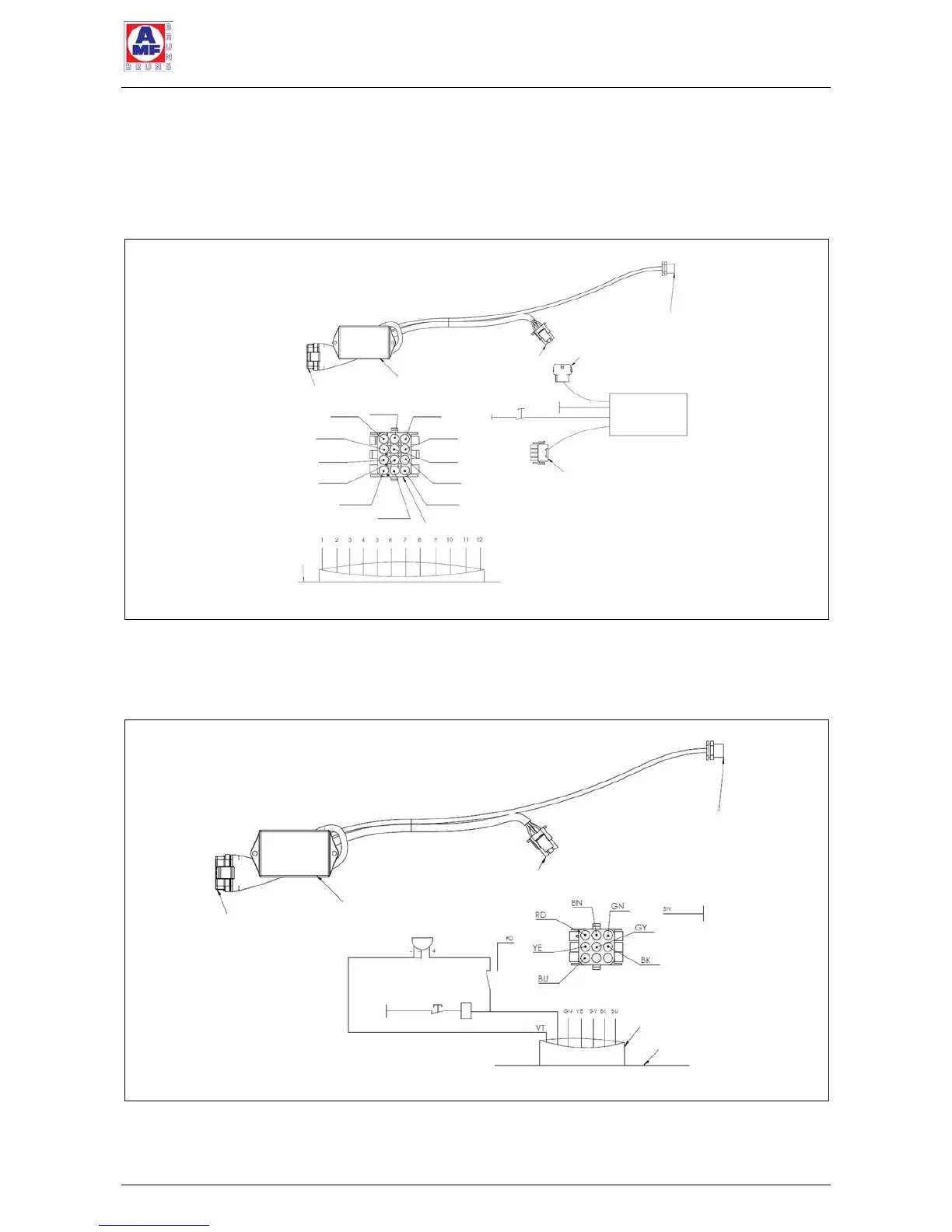
11 Electrical Circuit Diagrams
11.1 Electrical Circuit Diagram, Bluetooth
Remote Control K70 (optional)
Figure 53: Electrical Circuit Diagram, Bluetooth Remote Control K70
11.2 Electrical Circuit Diagram, Bluetooth
Remote Control K90 /K90A (optional)
Figure 54: Electrical Circuit Diagram, Bluetooth Remote Control K90 /K90 ACTIVE
Diagnosis connector
Control box
Connector from the remote control
Hand-held remote
control connector
Relay,
door contact
switch
Door contact switch
Earth
Cable to the lift
Vehicle floor
PIN 1
PIN 2
PIN 3
PIN 6
PIN 4
PIN 5
PIN 7
Earth
Buzzer
Connector to the lift
Diagnosis connector
Control box
Connector from the remote control
Hand-held remote
control connector
Connector to the remote control
Connector to the lift
Door contact switch
Earth
Connector from the lift
Vehicle floor
PIN 11
cable 11
PIN 1
cable 1
PIN 2
cable 2
PIN 3
cable 3
PIN 6
cable 6
PIN 4
cable 4
PIN 5
cable 5
PIN 7
cable 7
PIN 8
cable 8
PIN 9
cable 9
PIN 10
cable 10
PIN 12
cable 12
Control box K70

Table of Contents

Related product manuals