PAGE 29
NOTE: If the table contains unacceptable coordinate values, the display shows a “CONFIRM
FAILURE” message. Pressing ENTER key displays the unacceptable coordinate(s)
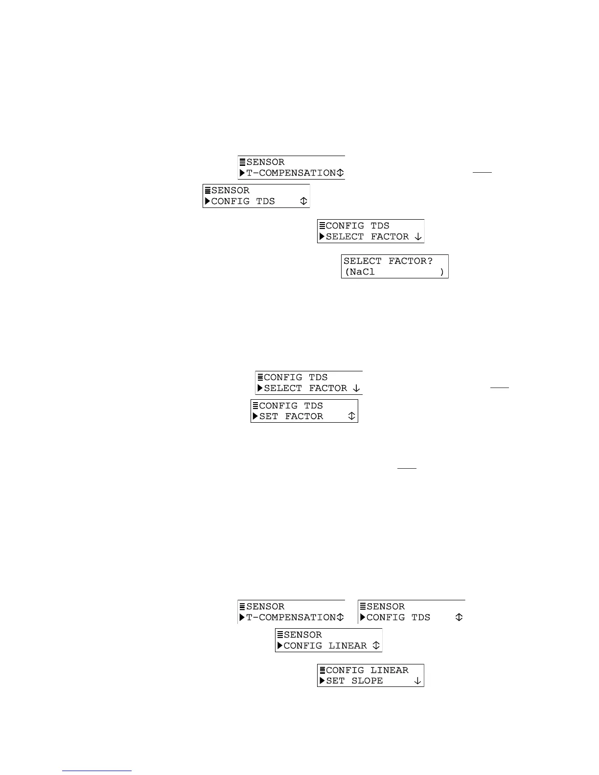
TDS Measurement Setup
Define the conductivity-to-TDS conversion factor:
1. With the
screen displayed, press
ØØ
ØØ
Ø
key once to display
.
2. Press ENTER key to display
.
3. Press ENTER key again to display
. Use
ØØ
ØØ
Ø and
××
××
× keys
to select a conversion factor, and press ENTER key to enter it:
• NaCl: Built-in NaCl conductivity-to-TDS conversion factor.
• USER DEFINED: Conductivity-to-TDS conversion factor set by user (see step 4).
4. If “USER DEFINED” was selected, you must set a conductivity-to-TDS conversion
factor:
A. With the screen displayed, press
ØØ
ØØ
Ø key once to
display .
B. Press ENTER key to display a screen like . Use arrow keys to adjust to a desired
conductivity-to-TDS conversion factor, and press ENTER key to enter it.
C. After the screen re-appears, press ESC key once to return to the screen.
CONFIG LINEAR or CONFIG T-TABLE Temperature Compensation (configuration not
needed for other compensation methods)
Only when LINEAR or TEMP TABLE is the selected temperature compensation, must the
transmitter be further configured. If the built-in NATURAL WATER properties table or NONE
was selected, disregard this subsection — no compensation configuration is needed.
LINEAR Compensation Setup
Factory defaults for LINEAR compensation are 2.00%/°C slope and 25.0°C reference
temperature. These values are appropriate for most aqueous solutions. Use chemical
handbook tables to find values for uncommon solutions. To enter different values:
1. With the
or screen displayed,
press
ØØ
ØØ
Ø key until screen appears.
2. Press ENTER key to display
.