POS MV V4 User Guide
Installation
Copyright © Applanix Corporation, 2009
2-12
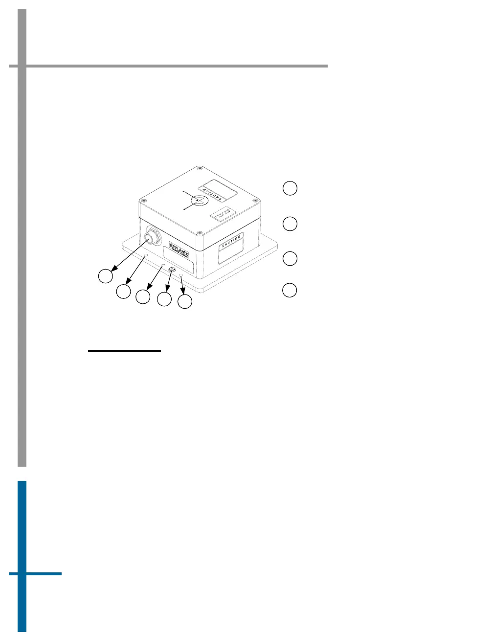
• Two holes are predrilled in the base to accept 0.25 in (6.35 mm)
diameter alignment pins. These holes maintain IMU alignment when
the unit is replaced, see
Figure 5.
Mounting holes accept
0.25 inch diameter bolt
Ground connection
screw
1
2
3
4
Power and data
connector
1
3
1
2
4
Hole for 0.25 inch
alignment pin
Figure 5: Typical IMU Mounting Features
Install the IMU
Once a suitable mounting location is selected, perform the following steps to
install the IMU:
1. Attach the IMU to the mounting location using four 0.25 in (6.35 mm)
pan head bolts inserted through the fixing holes in the base plate,
isolating the IMU from the hull by way of an electrically non-
conductive material if possible. Use flat and shake proof washers
under the IMU mounting screws. Ensure that the flat washers (not
shake proof washers) are placed in direct contact with the IMU base
plate.
2. Tighten the mounting bolts in a uniform manner, exercising care not
to over torque. Avoid warping the IMU base plate.