POS MV V4 User Guide
Installation
Copyright © Applanix Corporation, 2009
2-27
INTERFACE CONFIGURATION
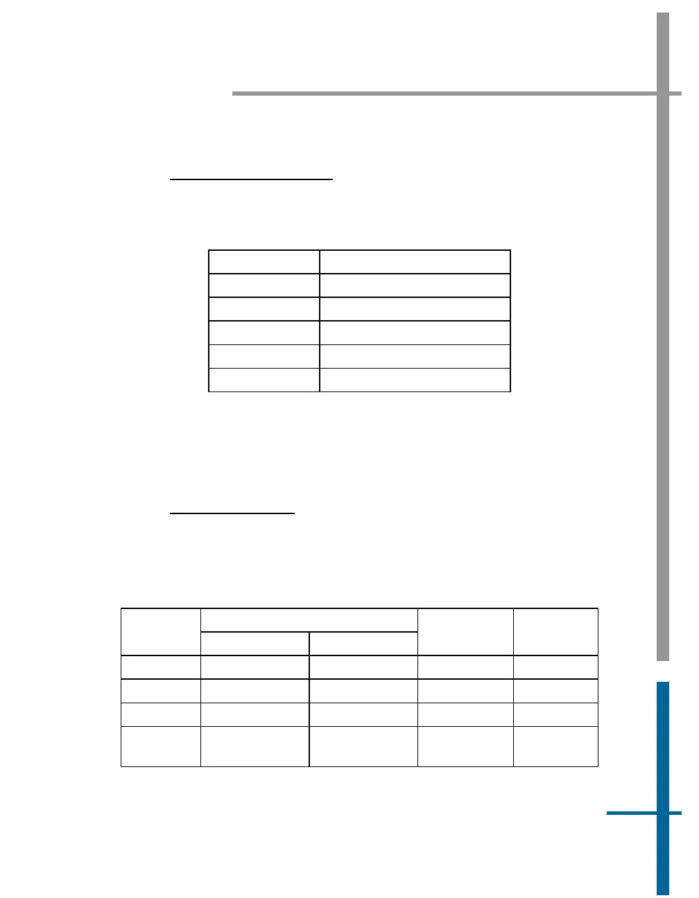
Table 7 identifies the configuration for the COM ports.
Table 7: COM Port Configuration
Setting Value
Baud Rate 2400 to 115200
Parity None, Even, Odd
Data Bits 7, 8
Stop Bits 1, 2
Flow Control Hardware, Software, None
GNSS 1 and GNSS 2 Interface
The serial digital port for each GNSS receiver provides access for receiver
upgrading of its software.
P
HYSICAL INTERFACE
Table 5, page 2-23 (POS MV V4-1) or Table 8 (POS MV V4) provides
connector pin assignments and mapping.
Table 8: GNSS Connectors Pin Assignment - POS MV V4
Pin Description
Pin
GNSS 1 GNSS 2
Signal Type
Signal
Direction
2 RX 1 RX 2 RS-232 Input
3 TX 1 TX 2 RS-232 Output
5 GND GND N/A N/A
1, 4,
6,7,8,9
N/C N/C N/A N/A