POS MV V4 User Guide
Installation
Copyright © Applanix Corporation, 2009
2-2
Table 5: I/O Connector Pin Assignment - POS MV V4-1
I/O Cable
Mapping
I/O Pin Pin Description
PIN Connector
Signal
Type
Signal
Direction
54 I2C Return N/A N/A
55 I2C +VIN N/A N/A
2 to 4;
12 to17;
50 to 55
Reserved
N/A
N/A N/A
* May be used for the TOV pulse output depending on the function assigned to the
port.
** External PPS In, Event 1 In and Event 2 In are optically isolated digital inputs.
** Inputs (and their return lines) are un-referenced and are independent of internal
POS MV V4-1 power supplies and GND.
** External PPS In can be controlled from an external 5 V TTL-level source capable
of supplying a minimum of 5 - 10 mA of sourcing or sinking current.
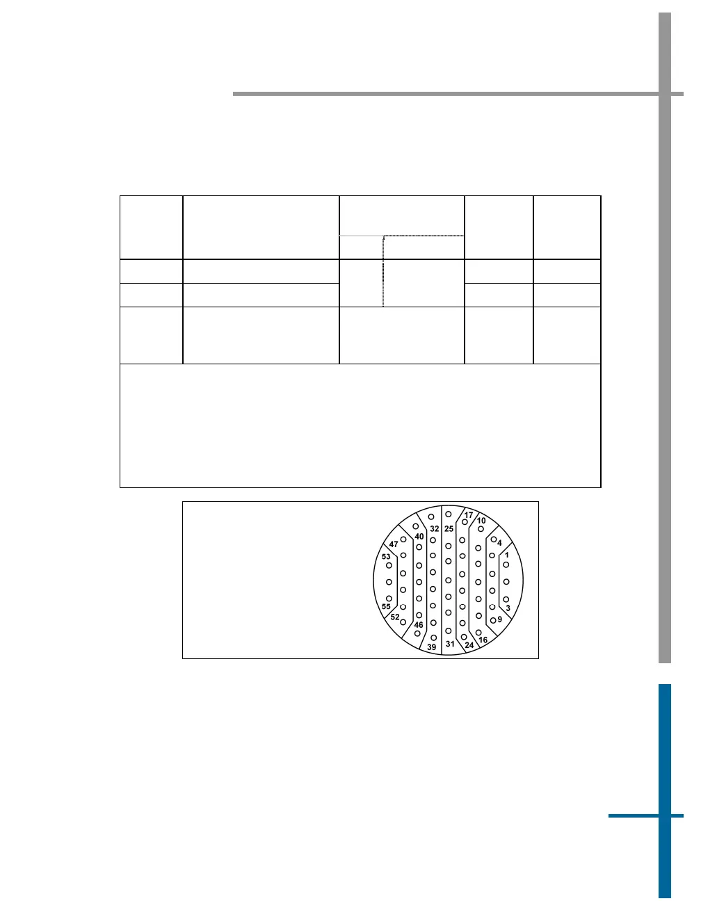
POS MV V4-1
Receptacle:
JD38999/24FE35SA
Cable Plug:
JD38999/26FE35PA
55 Pin
Figure 9: I/O Connector Pin Arrangement - POS MV V4-1