POS MV V4 User Guide
Installation
Copyright © Applanix Corporation, 2009
2-28
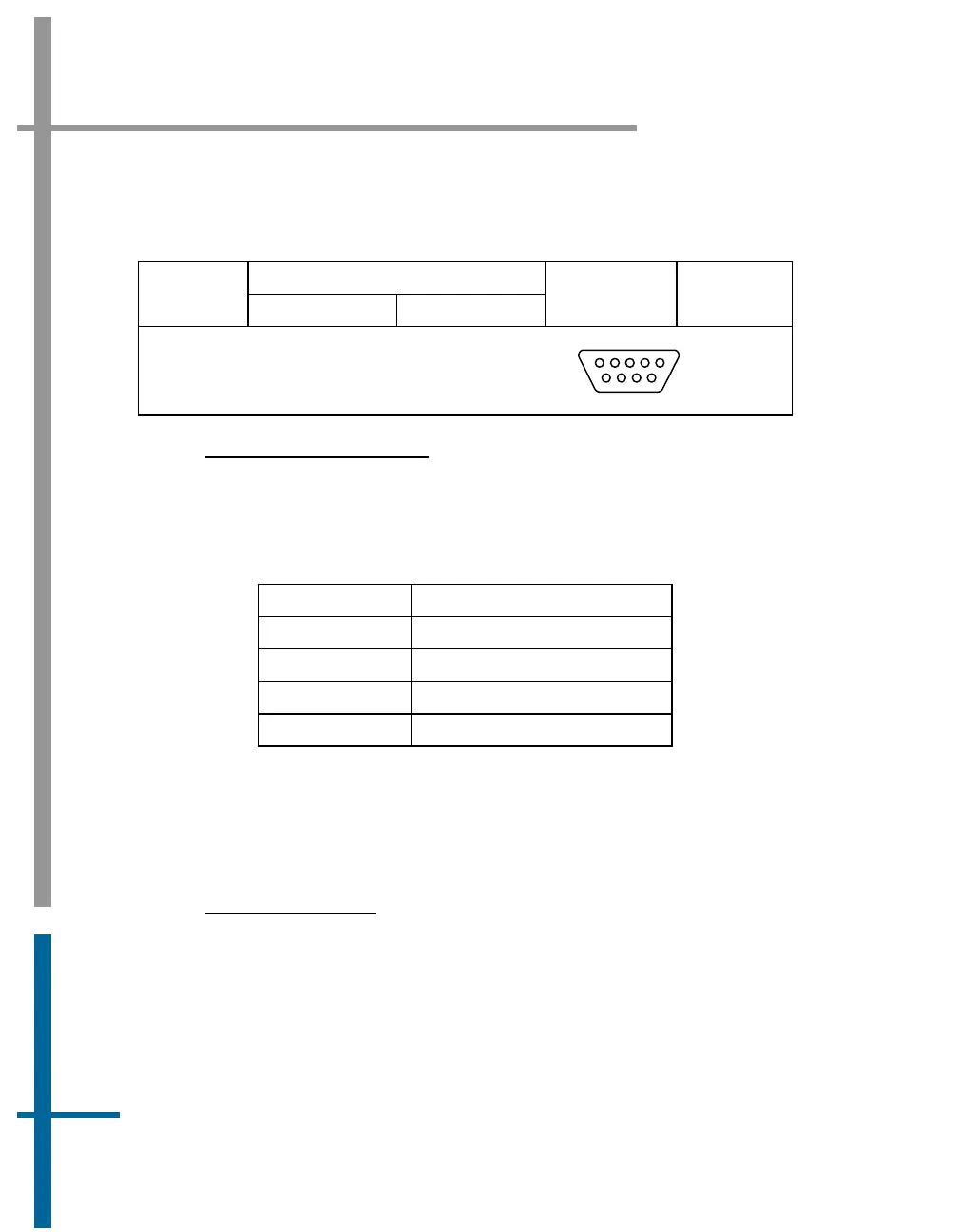
Table 8: GNSS Connectors Pin Assignment - POS MV V4
Pin Description
Pin
GNSS 1 GNSS 2
Signal Type
Signal
Direction
POS MV Rear Panel
DB-9P Male Connector
1
5
6
9
INTERFACE CONFIGURATION
Table 9 identifies the port configuration for the GNSS ports. These settings
may be changed using the MV-POSView software.
Table 9: GNSS Port Configuration
Setting Value
Baud Rate 2400 to 115200
Parity None, Even, Odd
Data Bits 7, 8
Stop Bits 1, 2
Events Interface
The Events digital port provides access to the POS MV V4 event timing
facility for events one and two.
P
HYSICAL INTERFACE
A cable that supports the two events is supplied with the system.
Table 5,
page 2-23 (POS MV V4-1) or
Table 10 (POS MV V4) provides connector pin
assignments and mapping.
To time tag an event with Universal Time Coordinated (UTC) or GPS Time,
supply a TTL level pulse whose rising/falling edge (configurable) corresponds